
Encoder Motor Speed Monitor
DEGREE OBJECTIVE 3
Develop mechanical control systems by implementing transducers, actuators, feedback, vision and sensing systems, and other mechanical systems into robotic platforms.
How it meets the objective: It implements the feedback half of motor control — a quadrature encoder (transducer) measures what the motor (actuator) is actually doing, computing live RPM independent of the commanded speed.
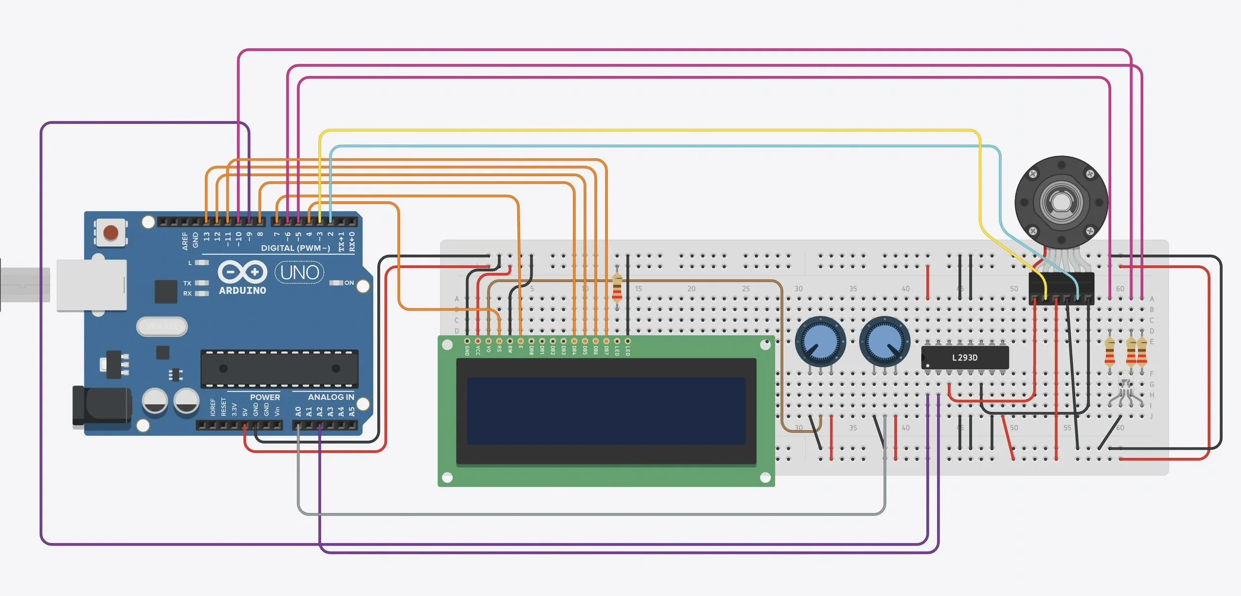
Live run: the pot throttle sets motor speed while the encoder measures actual RPM, with A/B channel levels, RPM, and PWM% on the LCD and speed bands on the RGB LED.
A DC motor driven by an L293D, with a quadrature encoder read via hardware interrupt — live RPM computed every 500 ms and reported on an LCD with RGB speed-band feedback. Built as an RBT173 free assignment in Arduino C++.
How it works
A potentiometer throttle sets PWM duty on the L293D enable pin. Channel A edges are counted two ways: an interrupt on every edge plus a polled edge counter in the main loop as a backup. Every 500 ms, the loop snapshots both counters — the interrupt count inside a critical section — takes whichever saw more edges, and converts edges to RPM using a calibrated count-per-revolution. The LCD shows live A/B logic levels on line one and RPM with PWM% on line two; an RGB LED maps speed to color bands.
Engineering highlights
Diagnosed a simulator limitation and engineered around it: Tinkercad stops delivering the external interrupt while the parallel LCD is active, silently killing the interrupt count. The fix counts edges redundantly and trusts whichever counter captured more in the window — on real hardware, both counters simply agree.
Calibrated measurement: counts-per-revolution derived empirically against the simulator's motor readout, with the recalibration procedure documented in the source.
Correct interrupt discipline: a volatile counter, minimal ISR body, and an atomic read-and-reset window — the standard pattern for interrupt-driven measurement.
Overflow-aware math: RPM is computed using unsigned long arithmetic to avoid silent 16-bit overflow.
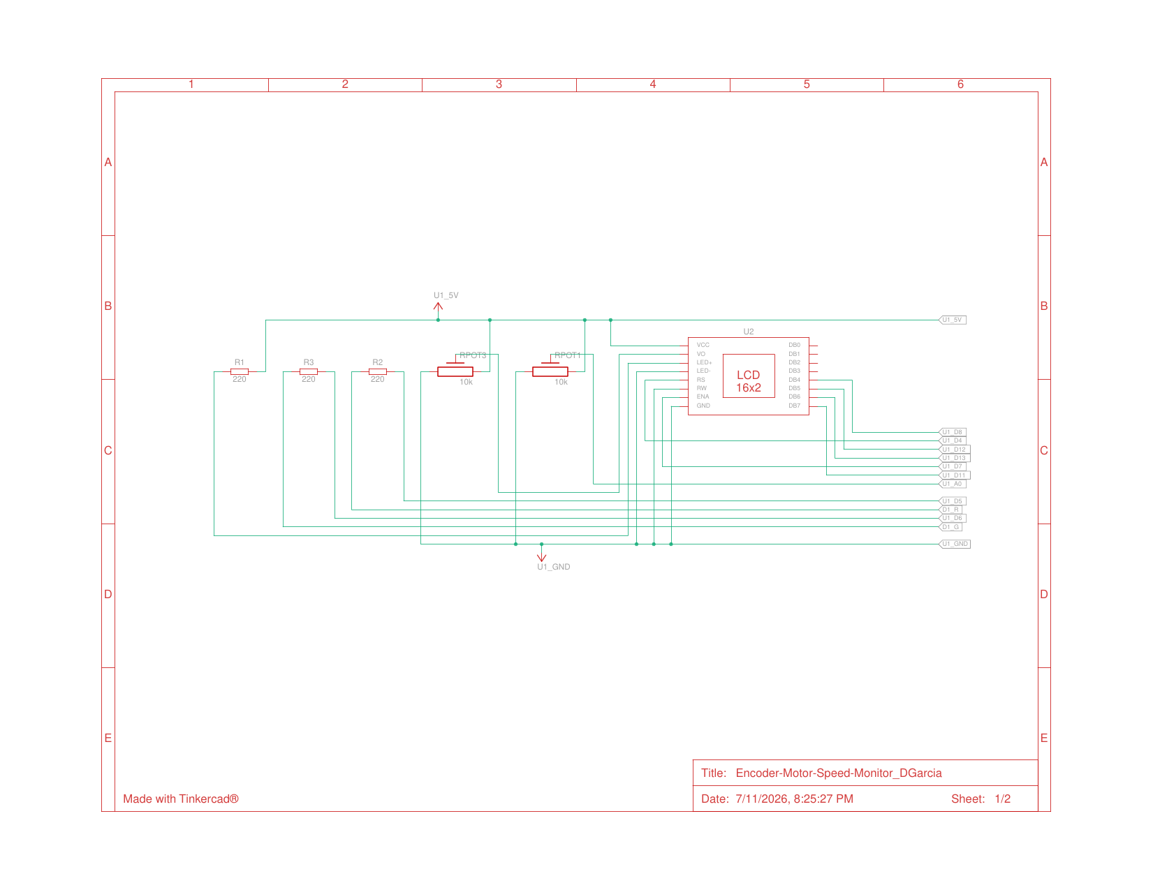
Display and controls: 16x2 LCD with a contrast pot, a throttle pot, and current-limiting resistors.
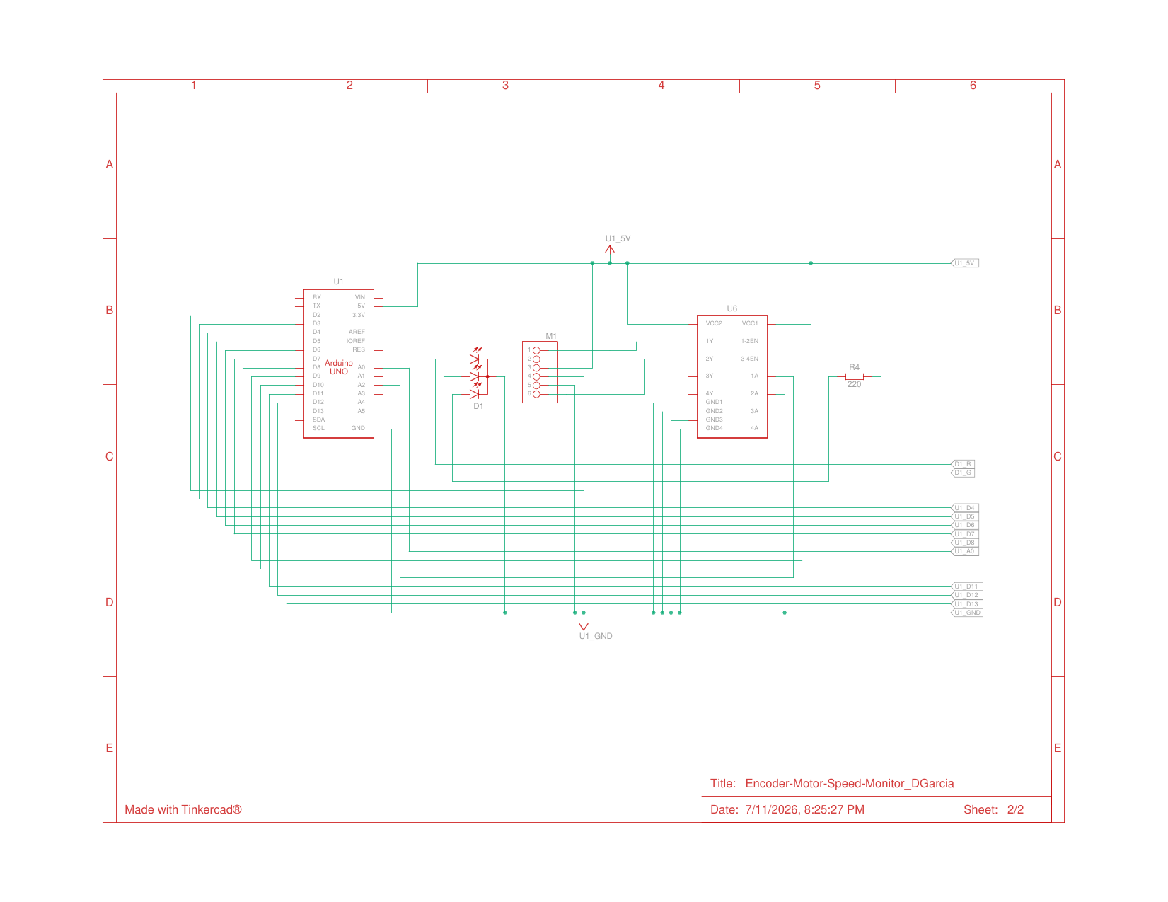
Drive and feedback: Arduino Uno, L293D H-bridge, DC motor with quadrature encoder, and the RGB status LED.