Engineering Process

Design decisions are only credible if the corrections are visible too.
This page documents how Subway Sentinel was actually engineered: what was tried, what failed, what the measurement said, and what changed because of it. The project moved from an early motion concept into a full Fusion 360 mechanical layout, then into structural screening, mass-property measurement, and a logged RobotStudio inspection cycle.
Every controlling dimension traces to a vendor drawing, a published source, or a measurement taken inside the CAD model. Where a value is a proxy or an assumption, it is labeled as one. That labeling discipline keeps the analysis results later in this page traceable and auditable at concept level.
All planned SIP engineering work is complete at digital-concept level, including mechanical CAD, EOAT mass properties, Rev B structural screening, measured-deck stability screening, and the fifteen-target RobotStudio inspection cycle. The completed RobotStudio cycle is published below. The final project showcase video is also complete and was submitted July 30, 2026.
Autodesk Fusion 360
Full mechanical assembly, generative design, mass properties, and static structural screening of the platform and tooling.
ABB RobotStudio
Station build, tool data entry, inspection path development, collision sets, and the logged motion validation run.
Source hierarchy
Vendor drawings outrank vendor marketing, measured CAD outranks estimates, and public models are labeled as either visual references or conceptual geometry proxies.
Documented assumptions
A running assumptions log tracks every frozen value, its confidence, and what would need to change before deployment.
The tunnel came first. Everything else was sized to fit inside it.
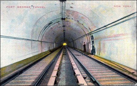
Subway Sentinel is built around the IRT Broadway–Seventh Avenue Line, the 1 line, in the Washington Heights deep-tunnel section near 168th, 181st, and 191st Streets.[10]
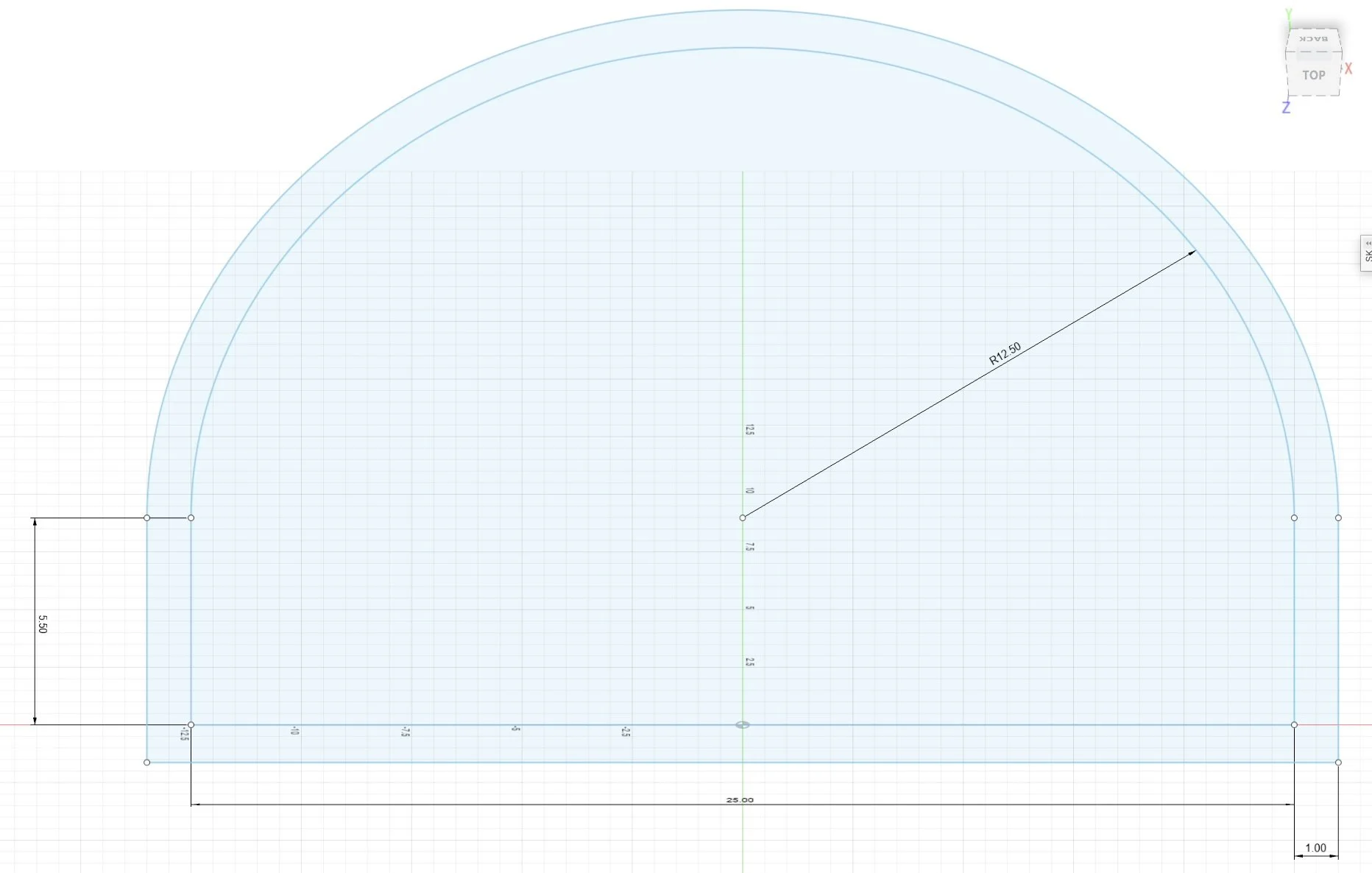
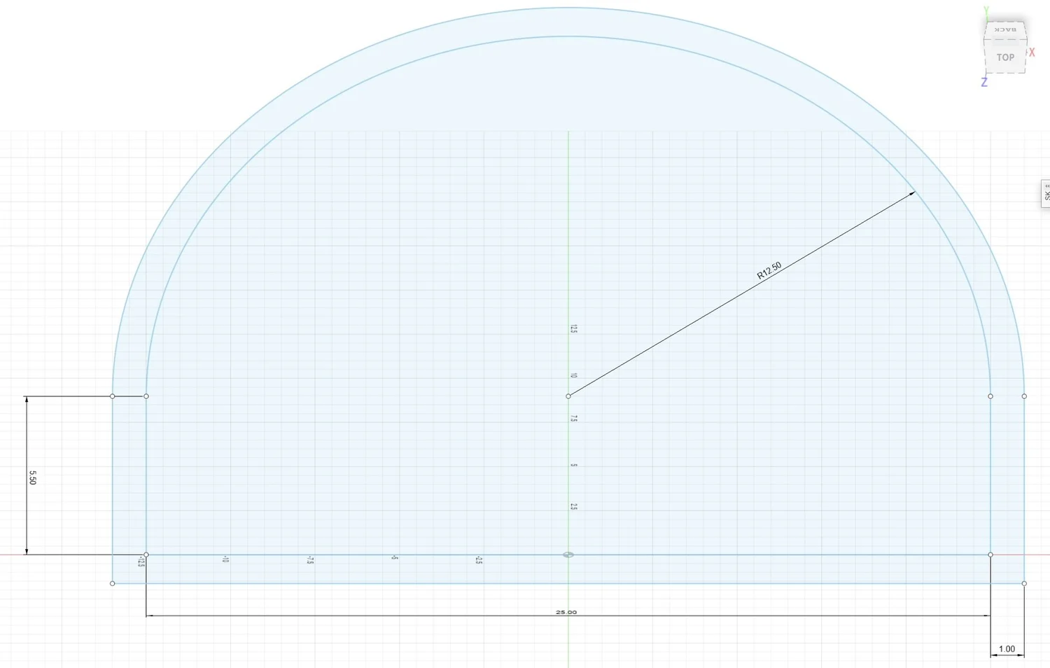
Research into the West Side Line showed the 1 line is not one tunnel type. It combines cut-and-cover subway, viaduct, and deep rock tunnel construction built by different contractors and methods. Modeling one generic tunnel would have produced a design that fits nowhere. The CAD baseline was narrowed to a typical two-track deep rock tunnel, roughly 25 feet wide by 18 feet high with 12-foot track centers, taken from historical IRT engineering references.[9]
Track gauge is modeled at standard gauge, 1,435 mm or 4 feet 8.5 inches, measured between the inside faces of the rail heads rather than between rail centerlines. The New York City Subway runs standard gauge across all divisions, the same as most North American railroads.[11]
Rail section took more digging. The current MTA qualified products list maintains fastener hardware for two running-rail sections in parallel, each with its own NYCT standard drawing series: 100-8, the modern designation for the 100 lb ARA Type B section the original IRT was built with, and the heavier 115RE.[12] Stocked quantities for 100-8 hardware run several times higher than 115RE, which indicates 100-8 remains the dominant installed section while 115RE appears in newer and heavier work. This project models 115RE with 1:40 inward cant as a modern concept baseline, drawn directly in Fusion rather than imported so gauge, cant, and rail-head geometry stay under project control. It is a design selection, not a claim that any specific location on the line carries that section.
Train clearance uses current MTA A-Division vehicle envelope dimensions from the open-gangway design requirements rather than a guessed car size.[8]
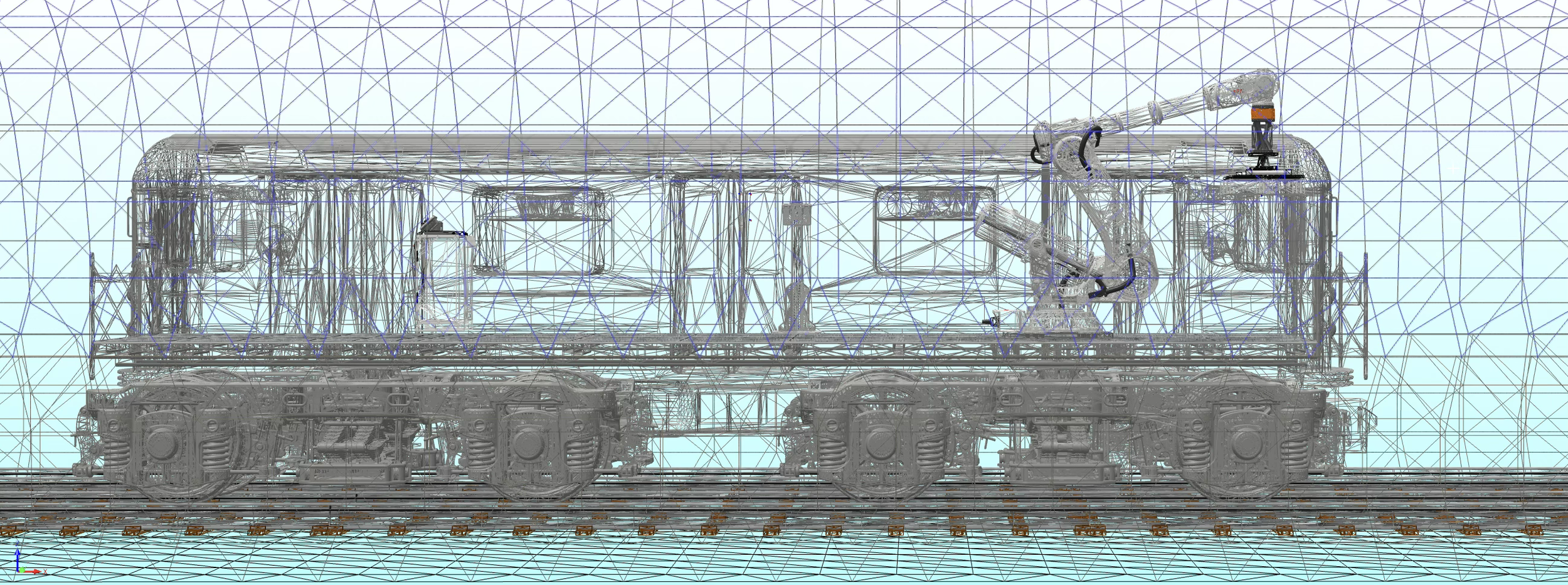
A scaled R62A source mesh provides visual scale only. Its dimensions were checked against a published R62A dimension sheet, then it was converted to SAT and STEP solely as RobotStudio scenery. It is excluded from collision and clearance acceptance; the simplified R262/A-Division envelope solid controls the static vehicle-clearance check.[8][13][14]
A frame that resists twisting, not just weight.
The rail platform is the core mechanical contribution. It carries the 1,780 kg ABB IRB 6750S-215/3.9, its OmniCore V250XT controller, the deck, and the inspection payload, and it has to stay stiff while the robot reaches sideways toward a tunnel wall.
The first structural decision was to stop trying to design a railcar. A full rail vehicle would require suspension, wheelset, braking, and certification work far outside this project's scope. Building on an existing bogie geometry kept the engineering effort on the parts that are actually new: the platform frame, the robot mounting structure, the tooling, and the validation chain.
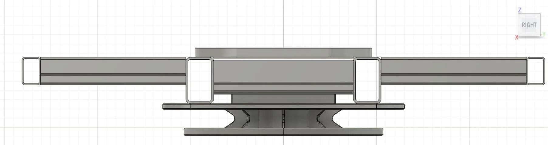
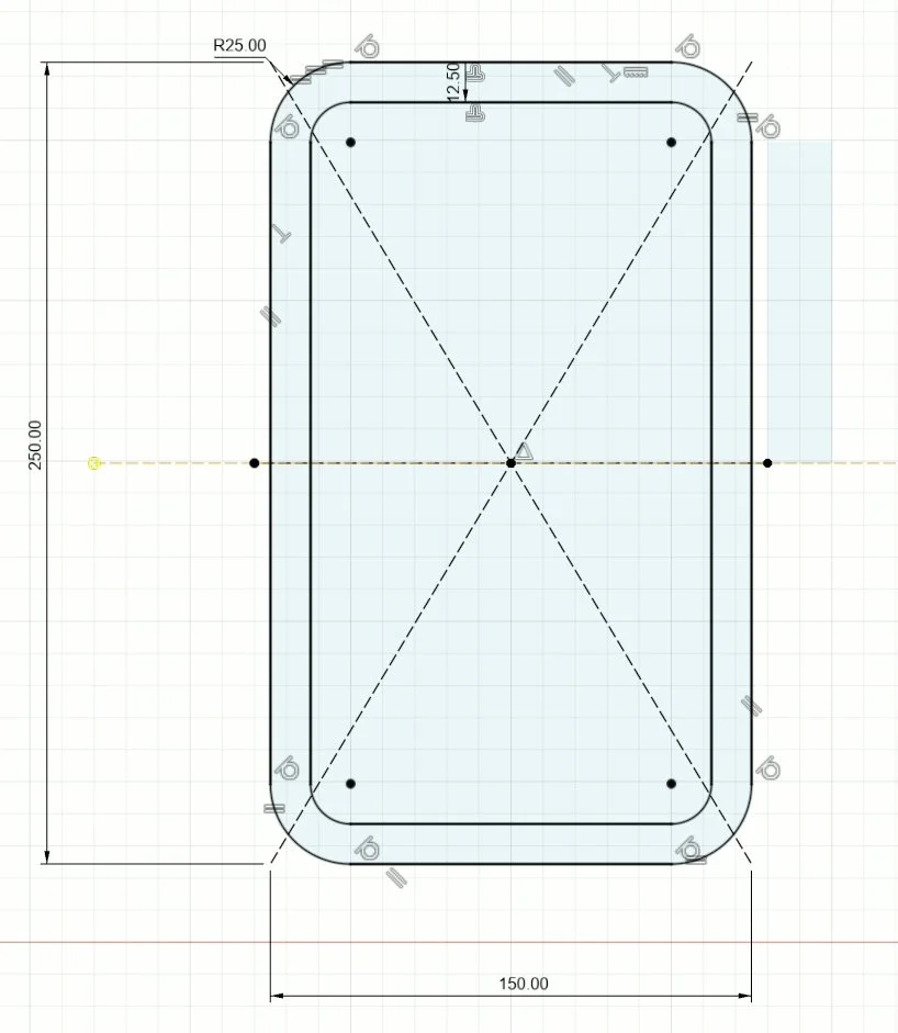
Because the dominant load is torsional rather than purely vertical, the frame uses closed rectangular sections instead of open beams. Closed sections carry torsion far better, which is well documented in chassis torsional stiffness studies.[15][16] Every structural member was sketched and dimensioned rather than approximated.
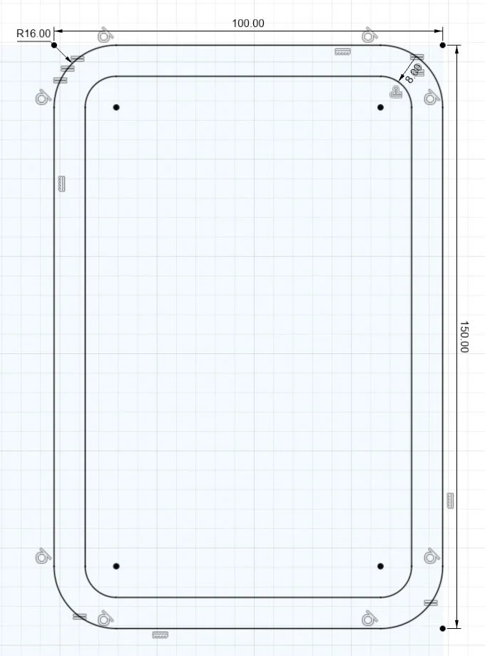
| Member | Section | Role |
|---|---|---|
| Main longitudinal rails | 250 × 150 × 12.5 mm | Primary bending and torsion path, 250 mm dimension vertical |
| Inner crossmembers, regular | 150 × 100 × 8 mm | Standard bay spacing across the inner frame |
| Inner crossmembers, heavy | 100 × 200 × 10 mm | Bogie interface and robot mounting zones |
| Outer main sections | 100 × 150 × 8 mm | Perimeter frame and deck edge support |
| Outer crossmembers, regular | 100 × 100 × 6 mm | Outer frame infill |
| Outer crossmembers, heavy | 100 × 150 × 8 mm | Outer frame load transfer zones |
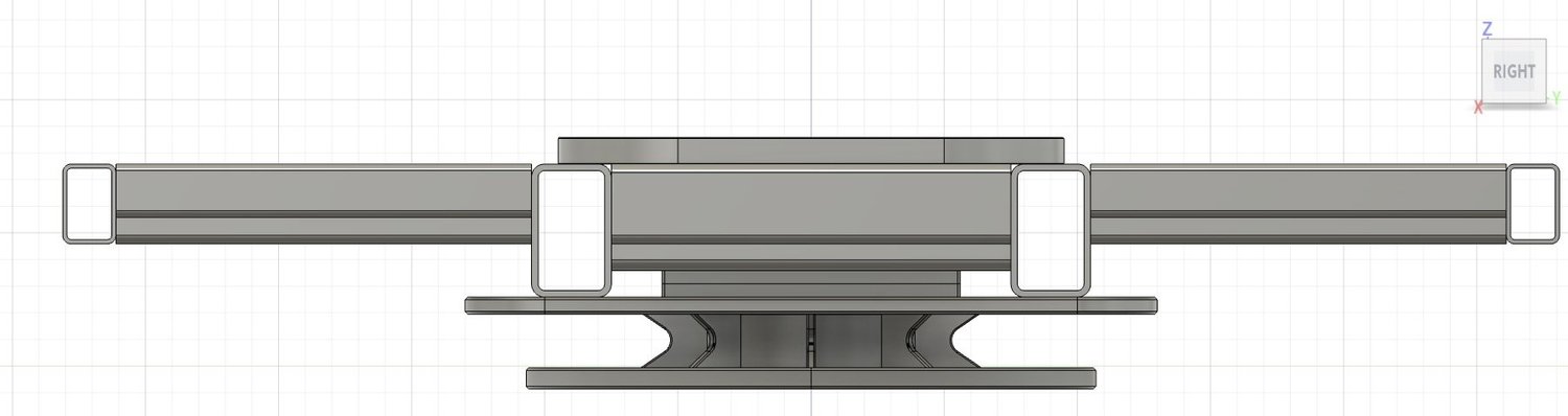
The robot mount is a structure, not a plate.
The ABB baseplate bolt pattern and fastener specification were taken directly from the robot manual.[2] From field experience, industrial robots at this size are normally raised on a pedestal rather than bolted flat to a deck, so the mount was developed as a welded torque box between the baseplate and the frame. The internal ribbing uses a star pattern to hold stiffness while removing mass, and gusseted ribs carry the load out into the bogie interface adapter.
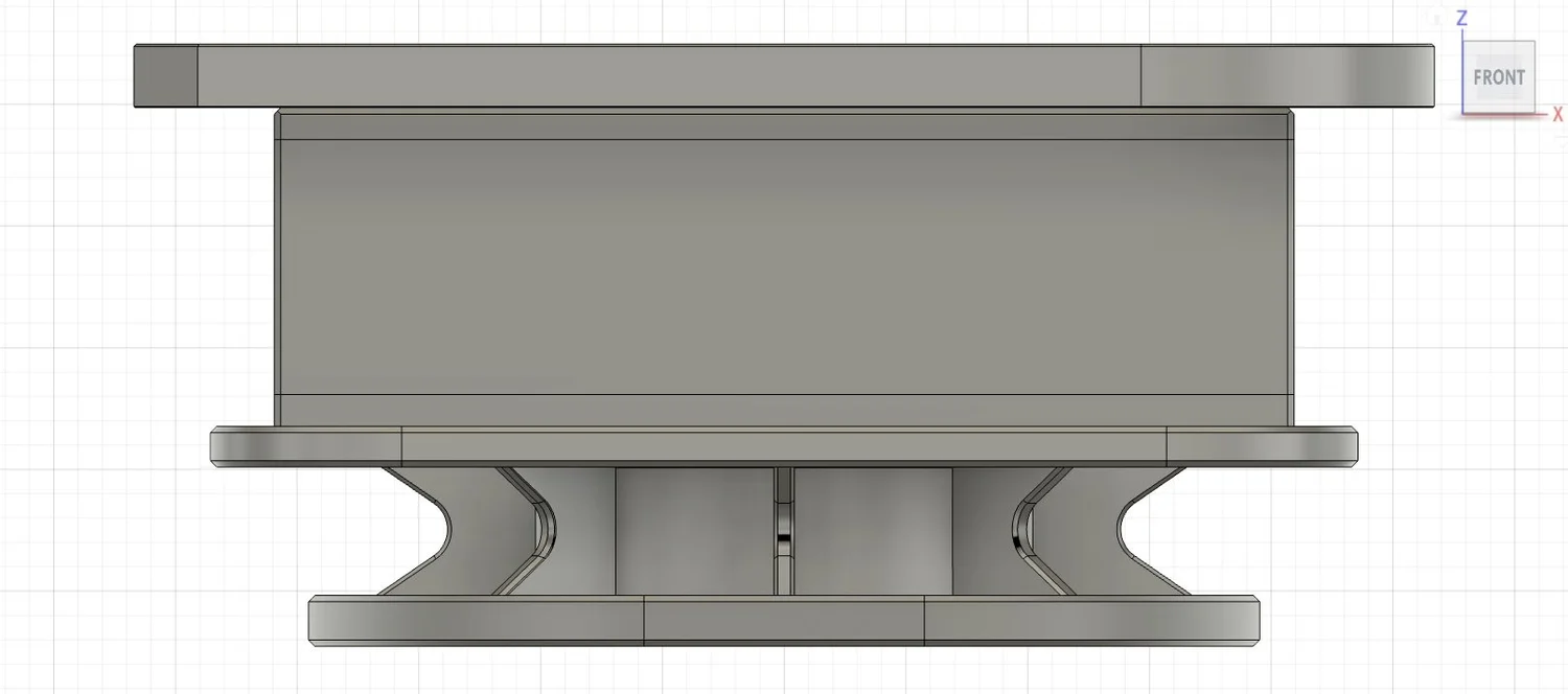
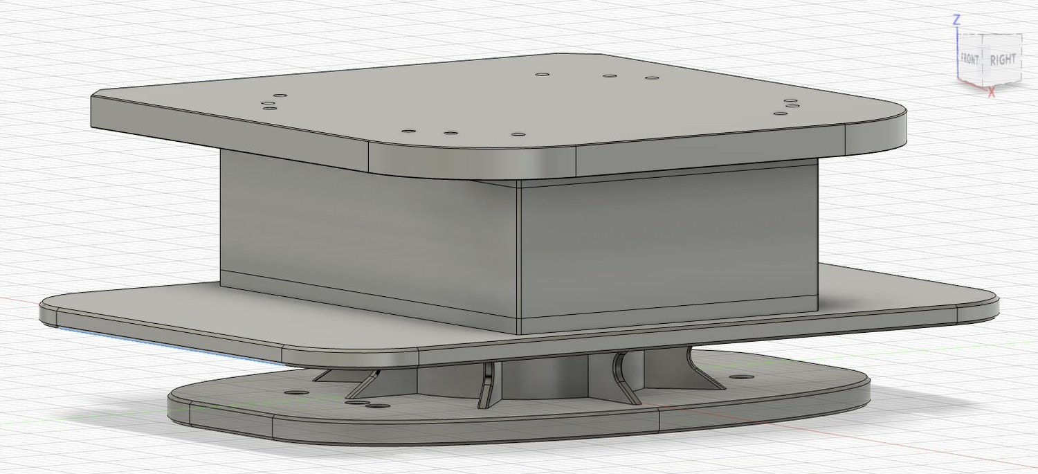
The deck is 30 removable panels of 8 mm tread plate, measured in CAD at 1,875 kg. That mass is not incidental. It sits low and centered, and adding it is what moved the worst-case stability result above the project threshold.
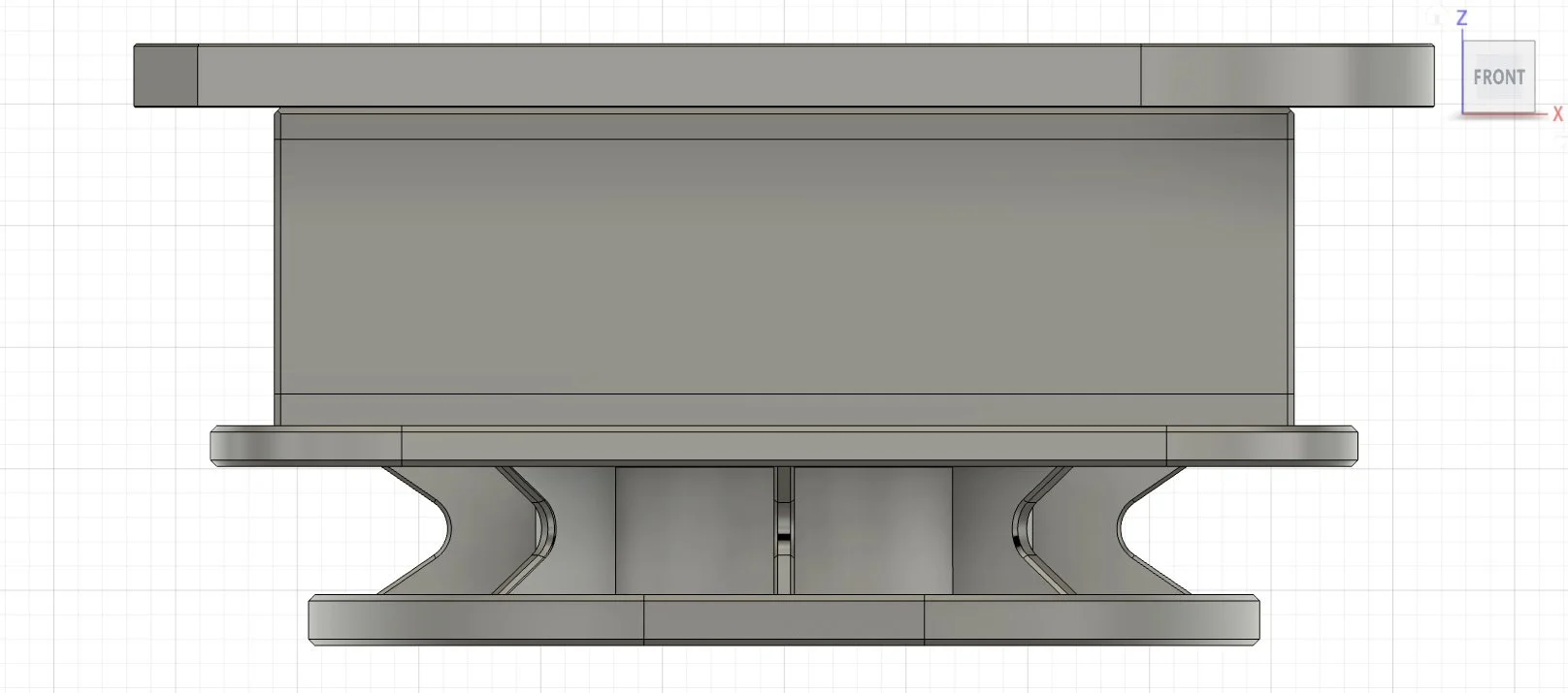
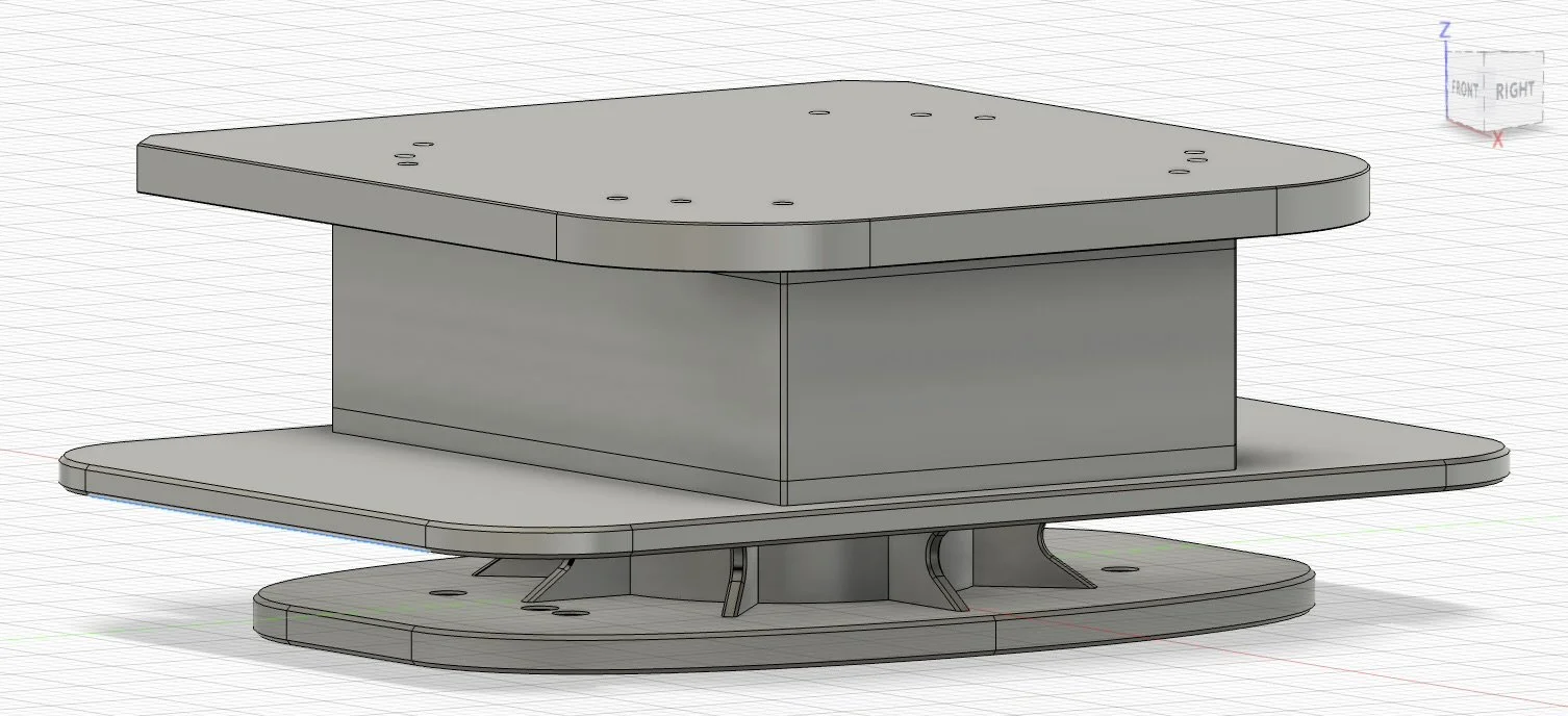
The bogie used in this study is a scaled TR22 reference, not an MTA bogie. After scaling to the modeled gauge its envelope is approximately 5,101.4 × 2,756.7 mm. The resulting platform width is 2,778.7 mm versus the 2,679.7 mm controlling A-Division/R262 width: 99.0 mm overall, or 49.5 mm per side, over the reference envelope. This known A-048 deviation also blocks sensor access to the lowest wall region. A production design would correct it using verified bogie geometry.
Every interface was dimensioned from the manufacturer's own drawing.
The ABB IRB 6750S-215/3.9 was selected for reach and payload after motion studies, then integrated through a tool changer, a custom wrist adapter, a generative-design bracket, and a carrier for the ground-penetrating radar.[1]
The ATI QC-160 tool changer was chosen partly from prior field experience with ATI hardware and partly through the manufacturer's Quick Consult selection tool, then confirmed against the official dimensioned drawing.[3][4] That confirmation mattered. The vendor selection guidance implied a direct mount, but the drawings show the ABB wrist uses a 100 mm H7 locating feature on a 160 mm bolt circle with eleven M12 fasteners, while the QC-160 customer interface uses an 80 mm H7 feature on a 125 mm bolt circle with ten M10 fasteners. Those patterns are not interchangeable, so a custom adapter plate was required: a 30 mm aluminum 7075 plate carrying both patterns, measured at 2.48 kg, with a flange-to-coupling stack of 85.423 mm. The adapter is concept geometry; no structural analysis is claimed for it.
The bracket was designed twice.
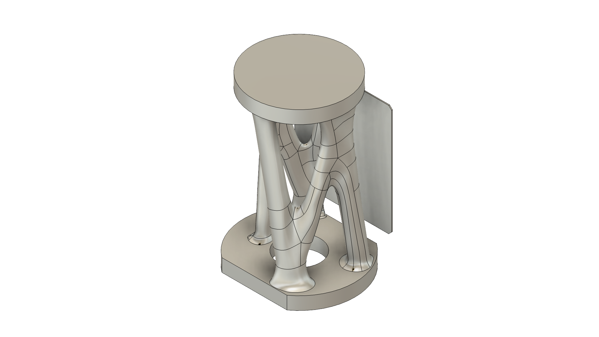
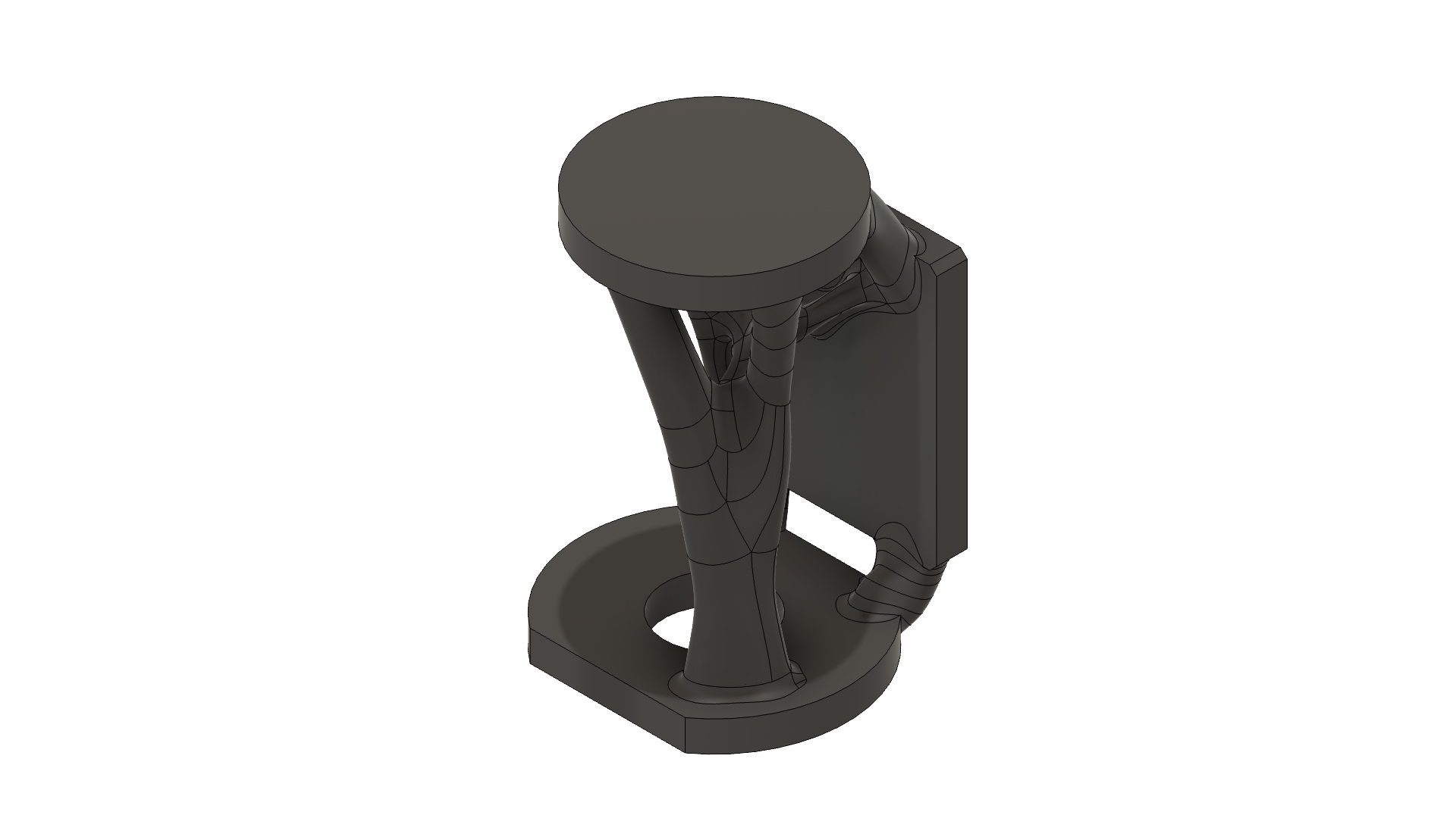
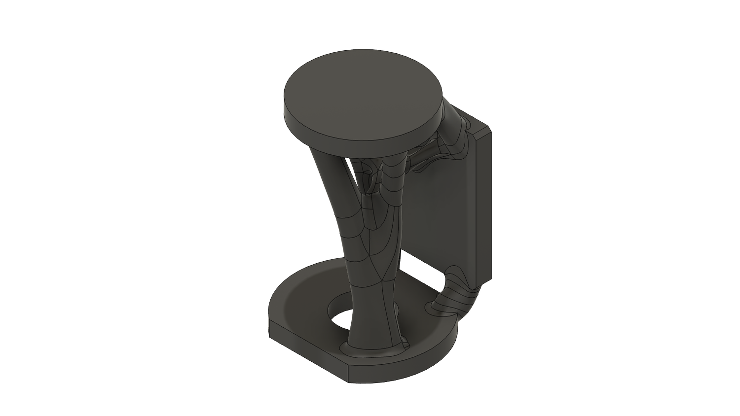
The bracket connecting the tool changer to the radar carrier was developed with Fusion's generative design solver. The first attempt was rejected. It used a generic dynamic load factor rather than published robot data, its moment axes did not rotate with the applied force, it had no load case for the tool hanging on its stand, and the side plate was too thin for the ATI hook adapter.
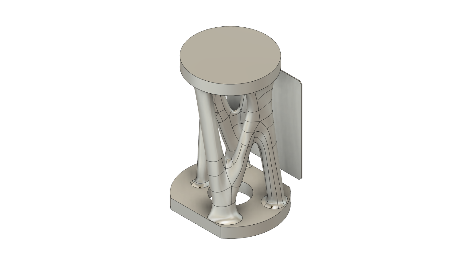
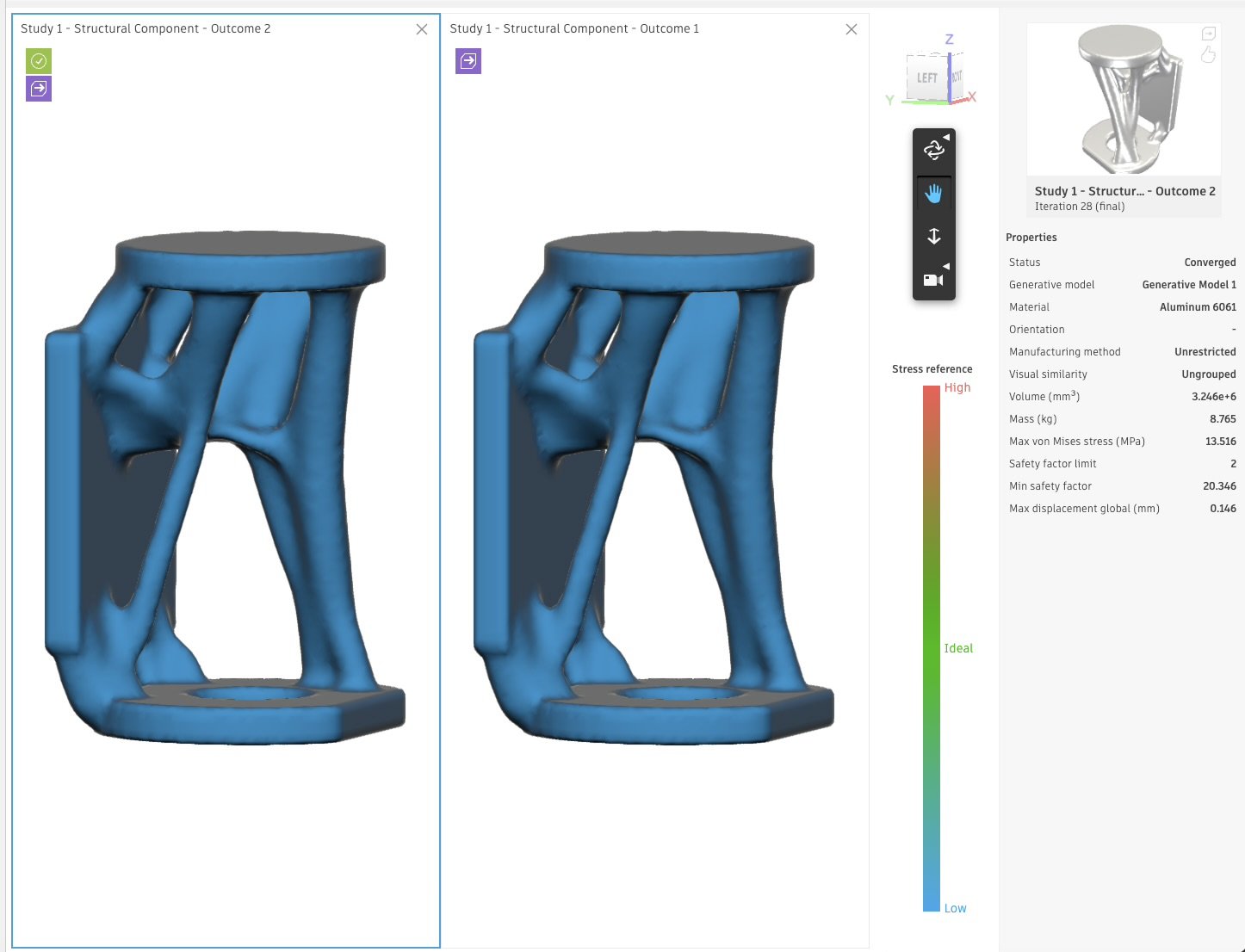
The study was rebuilt on ABB's published maximum emergency-stop acceleration of 45.3 m/s², applied in three orthogonal directions with the corresponding center-of-gravity offset moment rotated per case, plus a fourth load case representing the tool seated on the stand.[1] Two materials were run in parallel. Aluminum 7075 and 6061 produced effectively identical geometry, so 6061 was selected: lighter in this case, easier to machine, and consistent with the rest of the carrier.
The radar payload is modeled on the IDS GeoRadar Stream T in its full six-antenna configuration, a 35 kg contactless tunnel-inspection unit with 1.12 m coverage.[6] No CAD model was available from the manufacturer, and a direct request went unanswered, so the geometry was rebuilt from published dimensions and product imagery with internal volumes left hollow, so the modeled mass matches the published 35 kg rather than a solid-body estimate.[7]
The final RobotStudio flange-load record is 70.2 kg with center of gravity at (−3.1, 26.6, 412.1) mm, principal inertias of 7.611, 5.620, and 4.600 kg·m², and AOM quaternion [0.9926, 0.1209, 0.0048, 0.0073]. Those values pair the CAD-measured tool-side assembly and adapter with the vendor-specified 6.44 kg QC-160 Master mass so imported solid-model mass errors do not enter the robot load definition.
The reported bracket safety factor applies to the generated 6061 body, not the bolts, dowels, bearing interfaces, or QC-160 itself. ABB's 45.3 m/s² value is specified at nominal load center of gravity and lighter payloads may accelerate faster. Application-specific acceleration and joint verification remain future work.
Three load cases, one governing result.
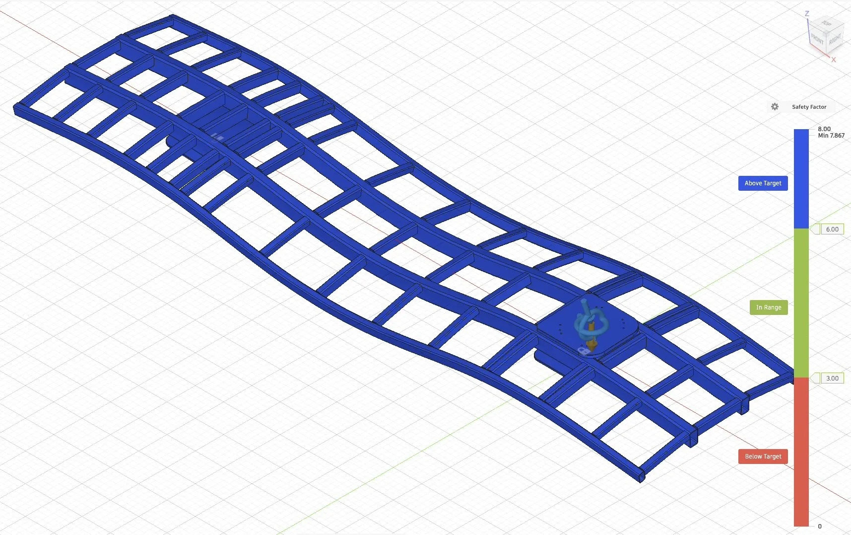
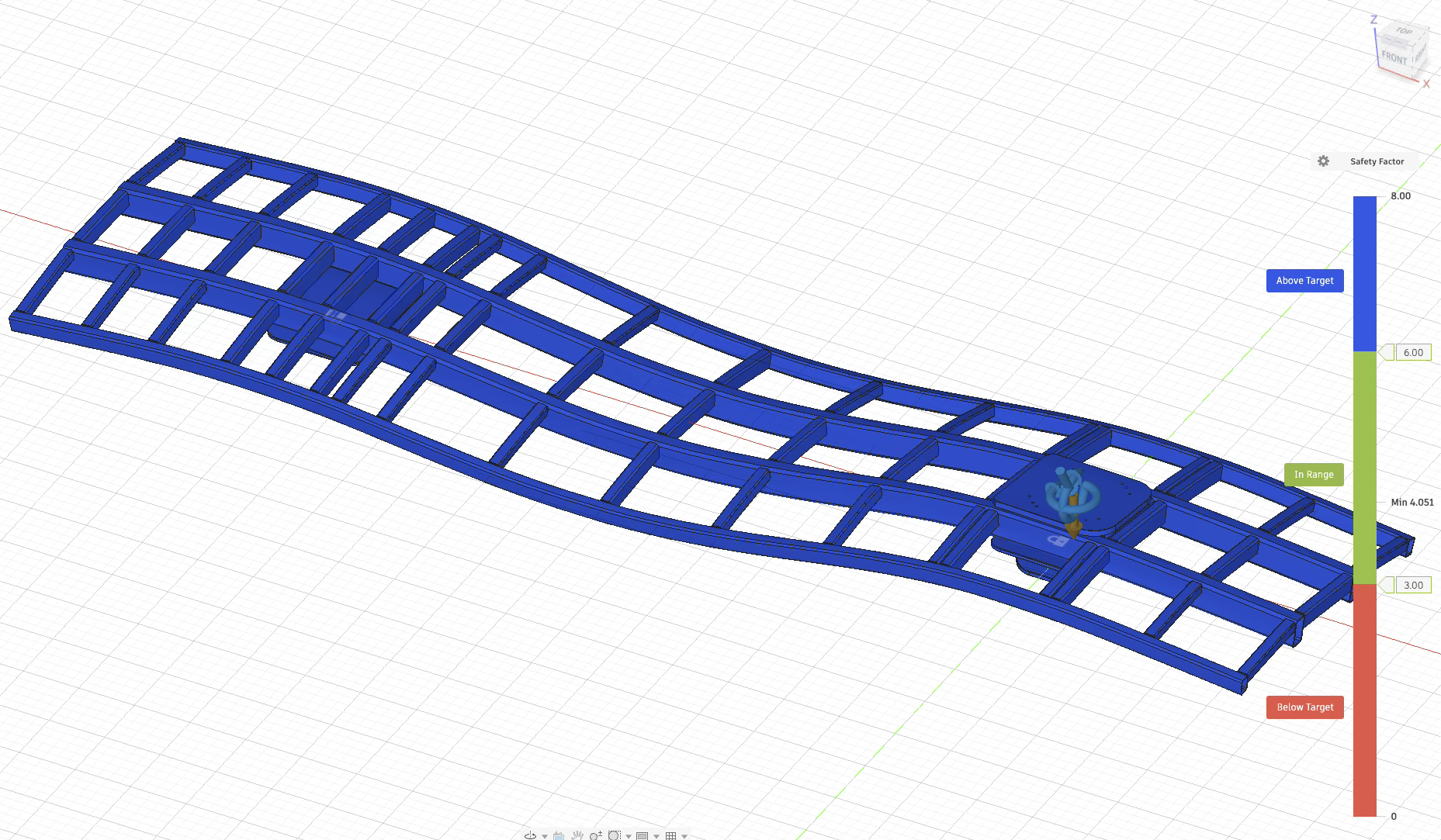
The platform was screened in Fusion using ABB's published foundation loads applied at the robot mounting plate, in both endurance and emergency-stop cases, across the two worst reach directions.[1][2]
Supports are idealized at the bogie adapter plates using a pin-and-roller-style scheme: the front adapter is fixed, and the rear is held vertically and laterally but free to move longitudinally. Fixing both ends would have made the frame artificially stiff. All analyzed solids use ASTM A572 properties with a 345 MPa yield; ASTM A500 Grade C remains the intended HSS specification for a future detailed design.
| Load case | Applied condition | Max stress | Deflection | Factor of safety |
|---|---|---|---|---|
| LC1 | Endurance, side reach | 43.8 MPa | 0.439 mm | 7.87 |
| LC2 | Emergency stop, longitudinal reach | 56.6 MPa | 0.391 mm | 6.09 |
| LC3 | Emergency stop, side reach (governing) | 85.1 MPa | 0.486 mm | 4.05 |
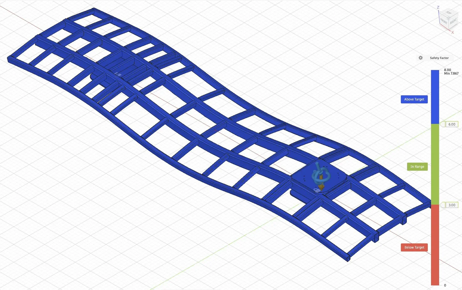
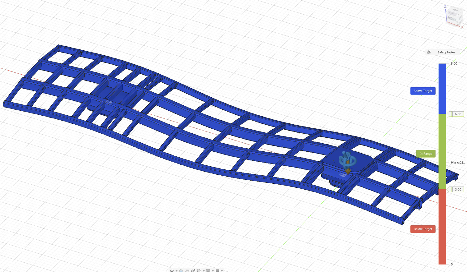
The first version of this study contained an error worth documenting. Reviewing the exported report showed that three moment vectors had resolved onto the wrong axes when they were defined by picking reference edges, which meant the predicted worst case, the side-tipping emergency stop, had never actually been solved. Correcting the axes and re-running increased the governing stress from 47.6 MPa to 85.1 MPa. The design still passed, but the first result was not the result it appeared to be.
This is simplified static screening, not structural certification. The Rev B study uses the default parabolic mesh without a documented convergence study and bonded contacts for the welded and bolted assembly. Welds, bolts, local bearing, fatigue, modal response, one-wheel torsion, suspension compliance, and moving-vehicle dynamics remain outside this result.
Stability was the harder problem.
Anti-tip stability was calculated separately as a rigid-body moment balance about the rail contact line at half gauge, comparing resisting moment against overturning moment. Before the deck was added, the realistic-bogie emergency-stop sensitivity case fell below the 1.5 target and indicated approximately 8.2 kN of hold-down.
That result conflicted with an operating requirement established through a subject-matter-expert interview with an MTA conductor: the inspection vehicle must remain in motion while scanning, so stop-and-clamp operation is not viable.[18] The concept response is to define intended SafeMove speed, acceleration, and reach limits rather than clamps; application-specific control validation remains open. Separately, adding the measured 1,875 kg deck to the rigid-body balance moved every screened case above the project threshold with no hold-down required.
| Scenario | Modeled bogie mass | Stability ratio | Hold-down required |
|---|---|---|---|
| Operating, motion-limited | CAD proxy | 4.98 | None |
| Operating, motion-limited | Literature-typical | 2.92 | None |
| Bounding, unrestricted emergency stop | CAD proxy | 2.58 | None |
| Bounding, unrestricted emergency stop | Literature-typical | 1.515 | None |
The 1.515 result clears the project criterion by about one percent. It is reported as a concept-level screening pass, not a certification, and it applies all published load maxima simultaneously even though the manufacturer states those maxima do not normally occur together. The workbook still carries the earlier 68 kg tool input and a conservative 2,500 mm lateral-reach placeholder; reconciliation to the final 70.2 kg load record and a measured worst RobotStudio pose remains open.
Payload chain
Tool-side assembly at 61.25 kg measured in CAD, plus the vendor tool-changer master at 6.44 kg and the measured 2.48 kg adapter.
Final flange payload record: 70.2 kg against a 215 kg nominal capacityTool changer moment
Modeled dynamic moment demand at the coupling under the ABB acceleration input, compared with the QC-160 rated moment for the full ten-fastener interface. Fasteners and joints require separate verification.
Approximately 1,054 N·m against a 2,710 N·m ratingThe inspection cycle, running.
The final RobotStudio station carries the tunnel, rails, platform, ABB IRB 6750S-215/3.9, OmniCore V250XT controller, tool changer, tooling, and tool stand, with the final 70.2 kg payload, center of gravity, inertia, and AOM active in the tool definition.
The inspection path sweeps fifteen targets from the platform-level sidewall to the tunnel crown at a constant 75 mm standoff, holding the radar face normal to the lining, at 200 mm/s with blended motion so the sweep is continuous rather than stopping at each target. Lower-wall and floor coverage are not claimed. Standoff was chosen within the sensor's published contactless capability.[6]
CollisionSet_1 checked the complete GPR tool against the tunnel geometry, the platform assembly, the robot links and base, and the V250XT cabinet. The logged program completed with zero collision events, zero singularity warnings, and no joint-limit or motion-supervision events across repeated cycles, and the sweep was also reviewed visually for contact. The train reference, wayside equipment, and cable routing were not modeled and are therefore outside that check. A signal-driven attach and detach sequence also demonstrates conceptual docking and drop-off logic, but a small reattachment offset remains; autonomous re-pick is not claimed as validated.
This is a digital-only concept with no physical prototype. The stationary twin demonstrates reach, path and tool-orientation control, and collision-free motion against the modeled tunnel and vehicle geometry. It does not validate moving-platform dynamics, clearance against unmodeled wayside equipment or cables, formal SafeMove configuration, GPR data quality, physical hardware behavior, or field safety.
What was tried, what failed, and what changed because of it.
This is the design trail rather than a highlight reel. Several of these entries are corrections found late, and they are included because catching them is part of the engineering.
01Tunnel geometry research
- Tried
- Modeling a single generic tunnel profile for the 1 line.
- Found
- The line combines cut-and-cover subway, viaduct, and deep rock tunnel construction. No single profile represents it.
- Decision
- Narrow the baseline to a typical two-track deep rock tunnel in the Washington Heights section and label it a public-source conceptual reference.
02Rail vehicle direction
- Considered
- Designing a custom railcar, adapting a maintenance flat car, or building on an existing bogie geometry.
- Found
- A full railcar would require suspension, wheelset, braking, and certification work outside the project scope, and a work flat car does not match a compact inspection platform.
- Decision
- Build the platform on an existing bogie reference so the engineering effort stays on the frame, tooling, and validation.
03Train and bogie reference models
- Tried
- Sourcing usable R62A car and bogie CAD.
- Found
- The available car model is a mesh, and official MTA bogie CAD was not available. Public bogie models were mostly wrong size or missing mounting features.
- Decision
- Convert the car mesh to SAT and STEP for RobotStudio scenery only, exclude it from collision and clearance acceptance, and use a simplified R262/A-Division solid for the static vehicle-envelope check. Select the TR22 bogie reference for interface development and document it as a proxy.
04Tool changer interface conflict
- Tried
- Mounting the selected tool changer directly to the robot wrist based on vendor selection guidance.
- Found
- The official drawings show different locating features, bolt circles, and fastener counts on each side. The interfaces are not interchangeable.
- Decision
- Design a custom 30 mm aluminum adapter plate carrying both patterns, dimensioned from both vendor drawings, and document it as a concept part pending a manufacturer-specific solution.
05Modeled mass errors
- Found
- CAD geometry does not carry real product mass unless someone makes it. Models are commonly built as solid material for visualization, and rebuilt geometry inherits whatever material the software defaults to. Several components in this project computed well above their published mass for that reason, in one case by an order of magnitude, and those figures would have propagated into the payload, stability, and interface calculations if taken at face value.
- Decision
- Treat modeled mass as unverified until checked. Calibrate rebuilt geometry so its mass matches published values, use the manufacturer's published mass wherever one exists, and confirm every imported component against its datasheet before that number enters a calculation.
06Structural analysis load direction error
- Found
- Reviewing the exported analysis report showed three moment vectors had resolved onto the wrong axes, so the predicted governing case had never been solved.
- Decision
- Correct the axis definitions, re-solve all cases, and republish. Governing stress rose from 47.6 MPa to 85.1 MPa and the design still passed, but the original result was not what it appeared to be.
07Stability failure and operating concept change
- Found
- Before the deck was added, the realistic-bogie emergency-stop sensitivity case fell below the 1.5 target and indicated approximately 8.2 kN of hold-down.
- Conflict
- Subject-matter-expert input established that the inspection vehicle must remain in motion while scanning, which rules out stop-and-clamp operation.
- Decision
- Define intended SafeMove speed, acceleration, and reach limits instead of clamps, while keeping application-specific controls validation open. Include the measured deck mass in the balance; all screened cases then pass with no hold-down.
08Generative bracket, first outcome rejected
- Tried
- Solving the tool bracket with a generic dynamic load factor and three motion load cases.
- Found
- The load basis was not traceable to published robot data, the moment axes did not rotate with the applied force, the docked condition was never loaded, and the tool-stand mounting plate was too thin for the hook adapter.
- Decision
- Rebuild the study on the manufacturer's published emergency-stop acceleration, rotate the moments per case, add a docked load case, and thicken the side plate. The final outcome is heavier and better supported within the generated-body study scope.
09Simulation tool attachment offset
- Found
- After each simulated tool exchange, the tool reattached a few millimeters out of position, and reseating it in the editor did not survive a simulation reset.
- Cause
- The saved simulation state and the stored attachment transform, not the robot program. The program placed the robot at identical positions for both release and pickup.
- Decision
- Correct the attachment while detached, rebuild the attachment, clear latched signals, and save a clean baseline state. The remaining cosmetic offset is documented rather than claimed as a validated exchange.
Ten key models from the assembly, open to inspect.
These are live Fusion 360 viewers. Drag to orbit, scroll to zoom, and use the browser panel to explore components.
Integrated system model
Tunnel, rails, train reference, bogies, platform, robot, and end-of-arm tooling working together as one assembly.
ABB IRB 6750S-215/3.9
Selected through reach, payload, and motion studies. Rated 215 kg at 3.9 m reach with a 1,780 kg robot mass.
Generative bracket, first outcome
Rejected: generic load basis, no docked load case, and a mounting plate too thin for the tool-stand hook adapter.
Generative bracket, final
Aluminum 6061 at 8.77 kg, solved with published emergency-stop loads and a docked case, with a thickened hook-adapter plate.
Tool changer master and wrist adapter
Custom 30 mm aluminum plate bridging the robot wrist pattern to the tool-changer pattern, dimensioned from both vendor drawings.
GPR end-of-arm tool
Radar carrier, generative bracket, tool-changer tool plate, and tool-stand hook adapter as one measured assembly.
Tool stand
ATI-based docking and drop-off concept supporting future multi-sensor tooling. The simulated autonomous re-pick remains unvalidated.[5]
Bogie reference
Scaled TR22 reference used for center pin, bolster, and side bearer interface development. Proxy geometry, not an MTA bogie.
R62A car reference
Source mesh converted to SAT and STEP for RobotStudio scenery only. Excluded from collision and clearance acceptance.[14]
Tunnel reference geometry
Conceptual deep two-track workspace used for platform layout and robot reach. A simplified R262/A-Division solid controls the static vehicle-clearance check.
Sources behind the design decisions.
Vendor documentation, transit references, published research, and public models used to develop and check this project. The full research record, including prior art and the assumptions log, is maintained separately.
- ABB. Product Specification, IRB 6750S, document 3HAC092903-001 Revision C. Robot variant selection, foundation loads, wrist flange interface, and maximum TCP acceleration.
- ABB. Product Manual, IRB 6750S, document 3HAC092901-001 Revision C. Installation, baseplate bolt pattern, fastener specification, and foundation requirements.
- ATI Industrial Automation. QC-160 robotic tool changer product page, including the Quick Consult selection tool used during component selection. ati-ia.com
- ATI Industrial Automation. Dimensioned drawing 9630-20-160, QC-160 tool changer. Interface patterns, stack height, and fastener-dependent moment ratings.
- ATI Industrial Automation. Tool stand components: ATI-9121-TSL-TH-5641 hook plate and ATI-9120-TSL-PM-248H-R000 post module, with drawings 9630-20-TSL-TH-5641 and 9630-20-TSL-RMH-R000.
- IDS GeoRadar. Stream T contactless tunnel-inspection radar product page. Mass, envelope, coverage, and contactless standoff capability. idsgeoradar.com
- IDS GeoRadar. Stream T product brochure, six-antenna full configuration. Manufacturer CAD was requested directly and not received, so the geometry was rebuilt from published dimensions and product imagery.
- Metropolitan Transportation Authority. A-Division open gangway car design requirements. Vehicle envelope widths and roof height used for clearance study. mta.info
- Engineering Features of the New York Subway. Historical engineering reference for deep tunnel dimensions and track centers on the original IRT.
- nycsubway.org. IRT West Side Line history, construction methods, and archival photographs including the Fort George Tunnel. nycsubway.org
- nycsubway.org. Subway facts and figures, confirming system track gauge of 4 ft 8.5 in, standard gauge, across all divisions. Reference
- Metropolitan Transportation Authority, New York City Transit. Qualified Products List, July 2026. Maintains fastener hardware and NYCT standard drawing series for both 100-8 rail (T-2018 series) and 115RE rail (T-5018 series), with stocked quantities indicating 100-8 remains the dominant installed section. mta.info
- nycsubway.org. R62A car dimension sheet, used to correct the scale of the reference model. Dimension sheet
- Sketchfab. NYCT R62/R62A subway car model, used as a visual scale reference only. Model source
- Chassis Frame Torsional Stiffness Analysis. International Journal for Scientific Research and Development. Torsional behavior of ladder frame structures. Paper
- Dowswell, B. “Torsion of Rectangular HSS and Box Section Members: A Critical Review.” Engineering Journal, American Institute of Steel Construction, 2026, DOI 10.62913/engj.v63i1.1364. Used for closed-section torsional behavior, not structural qualification. AISC Engineering Journal
- Modal analysis and frequency matching study of subway bogie frame under ambient excitation. Scientific Reports. Background on bogie structural dynamics. Paper
- Subject-matter-expert interview. MTA conductor, twelve years of service, licensed on all system trains. Interview conducted July 9, 2026, covering current inspection practice, crew structure, and the continuous-motion operating requirement.
Prior art, the complete assumptions log, and dated decision records are maintained in the controlled project archive. See the innovation brief for the sixteen prior-art references reviewed during this project.