
SUBWAY SENTINEL · UAT STUDENT INNOVATION PROJECT
Inspect what the subway hides.
A concept-level rail inspection platform combining an ABB industrial robot and ground-penetrating radar to study safer, repeatable inspection of subsurface subway infrastructure.
Make difficult tunnel inspection more repeatable—and keep people farther from the hazard.
Much of the infrastructure beneath subway tracks cannot be evaluated through visual inspection alone. Subway Sentinel explores how a rail-mounted robotic platform could position ground-penetrating radar along track-bed and tunnel interfaces while the inspection vehicle remains in motion. The goal is not to replace engineering judgment; it is to create a consistent robotic workflow that can support better inspection data and reduce repetitive exposure in confined tunnel environments.
One platform. Four integrated engineering layers.
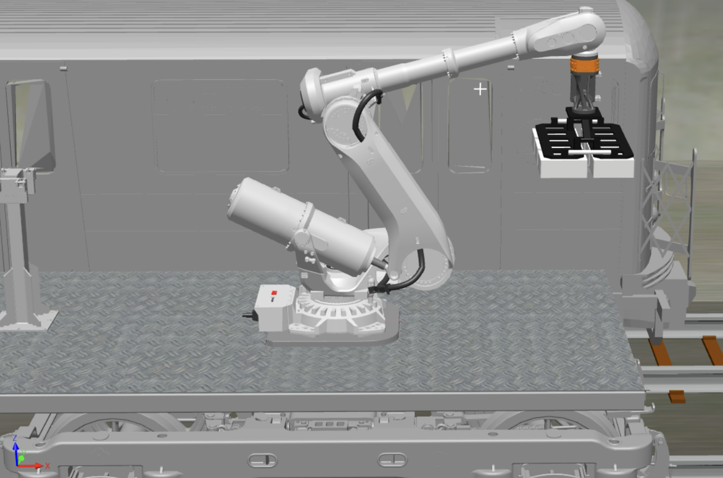
The project connects mechanical design, industrial robotics, automated tool handling, and subsurface sensing into a single digital prototype sized around an NYC A-Division tunnel reference envelope.
Rail Platform
A welded steel frame and pivoting bogie interfaces carry the robot, controller, and inspection equipment on standard gauge, 1,435 mm.
ABB IRB 6750S
A long-reach industrial robot positions the inspection tool around the track and tunnel envelope.
ATI QC-160
A robotic tool changer supports the GPR carrier and the concept tool-stand architecture.
IDS Stream T GPR
A calibrated digital sensor model represents a 35 kg multi-channel ground-penetrating radar unit.
Designed around continuous motion instead of stopping in the tunnel.
The operating concept was revised after a July 9, 2026 review with a 12-year MTA conductor licensed to operate every train in the system: the vehicle continues moving while intended SafeMove-style speed, acceleration, reach, and clearance controls constrain the robot inspection cycle. Application-specific SafeMove validation remains future work.
Move through the inspection corridor
The rail platform provides the moving reference while remaining inside the documented tunnel envelope.
Position the GPR sensing face
The robot controls sensor orientation and offset relative to the selected track-bed or tunnel inspection surface.
Maintain a constrained scan path
RobotStudio validates the 15-target sidewall-to-crown sweep with the final tool data, controlled orientation, 75 mm standoff, and modeled-station collision checking.
Review the digital evidence
CAD, structural screening, stability calculations, and simulation results are documented together as a concept-level engineering record.
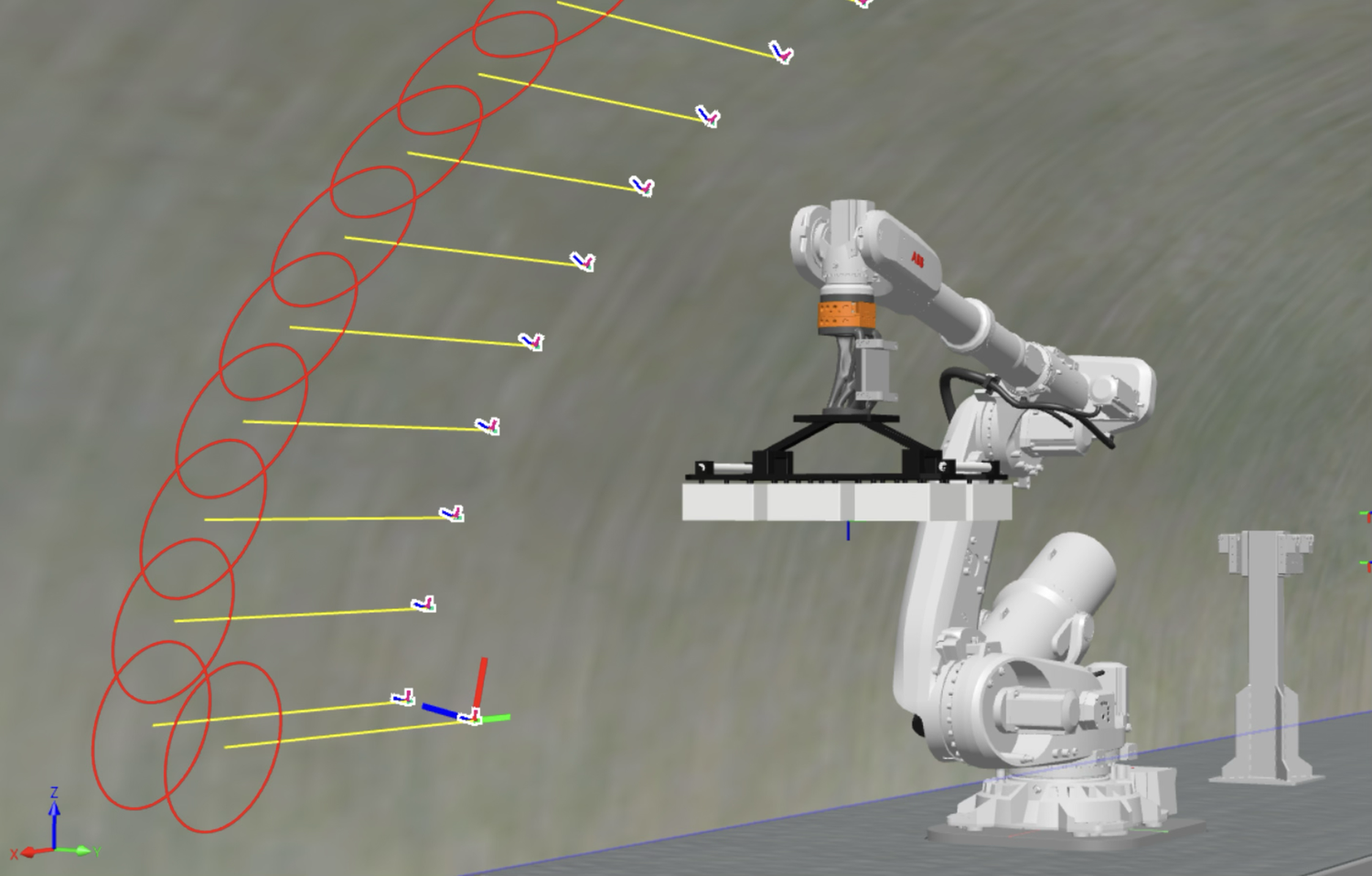
This view illustrates the completed 15-target sidewall-to-crown path. The logged digital run checked reach, orientation, joint limits, singularities, and modeled-station collisions; it does not prove field safety.
The concept is supported by engineering evidence—not just a final render.
The current design was checked through ABB-sourced load cases, static structural simulation, rigid-body stability calculations, vendor interface drawings, and measured CAD mass properties.
Three ABB foundation-load cases
The corrected side-reach emergency-stop case governed at 85.1 MPa with 0.486 mm maximum displacement.
Result: FoS 4.05 · screening target ≥ 3.0Operating and bounding cases pass
With the measured 1,875 kg deck included, the minimum realistic-bogie emergency-stop stability ratio is 1.515.
Result: ratio 1.515 · project target ≥ 1.5Measured mass-property chain
The combined robot payload is 70.2 kg with a mass-weighted combined center of gravity at (−3.1, 26.6, 412.1) mm from the flange.
Result: payload remains well below 215 kg ratingQC-160 moment screening
The modeled tool-side dynamic moment is approximately 1,054 N·m against the 2,710 N·m QC-160 rating using the full ten-fastener interface.
Result: concept-level moment margin ≈ 2.6The engineering concept, inspection cycle, and final showcase video are complete.
This page is a concise snapshot; the Engineering Process page carries the dated decisions, assumptions, audit history, and weekly evidence.
July 18: Platform FEA Rev B closed. July 19: The measured deck closed the anti-tip screening and the final payload/inertia record was completed. July 23: Motion Cycle 2 completed with zero logged collision, singularity, or joint-limit events, and the Criteria A–E matrix reached 23 of 23 verified items. July 30: The final project showcase video was completed and submitted.
Requirements and architecture
System boundaries, reference tunnel, robot selection, and MVP scope.
CompletePlatform and EOAT CAD
Rail frame, deck, ABB interface, QC-160 adapter, GPR carrier, and tool-stand concept.
CompleteStructural and stability checks
Platform FEA, payload chain, QC moment screening, and anti-tip workbook.
CompleteRobotStudio inspection cycle
Final tool data, 15-target sidewall-to-crown path, reach, orientation, collision, singularity, and joint-limit review.
CompleteFinal project showcase video
CAD, analysis, RobotStudio, VR footage, limitations, and the final concept narrative were completed and submitted July 30, 2026.
CompleteA credible concept includes what has not been proven yet.
Subway Sentinel is a digital design study, not a certified or field-ready subway maintenance vehicle. The work demonstrates a technically grounded integration direction and identifies the next validation steps required before any physical deployment.
No physical prototypePerformance is based on CAD, simulation, vendor data, and preliminary engineering calculations.
Screening-level analysisProduction design would require refined joint, weld, fatigue, modal, mesh-convergence, and wheel-load validation.
Known envelope and deployment workThe current 2,778.7 mm platform is 99.0 mm wider overall than the 2,679.7 mm A-Division reference—approximately 49.5 mm per side—because the scaled TR22 bogie is a proxy. Production use requires verified bogie geometry, MTA review, tunnel testing, formal risk assessment, controls validation, and applicable rail and machinery safety compliance.