
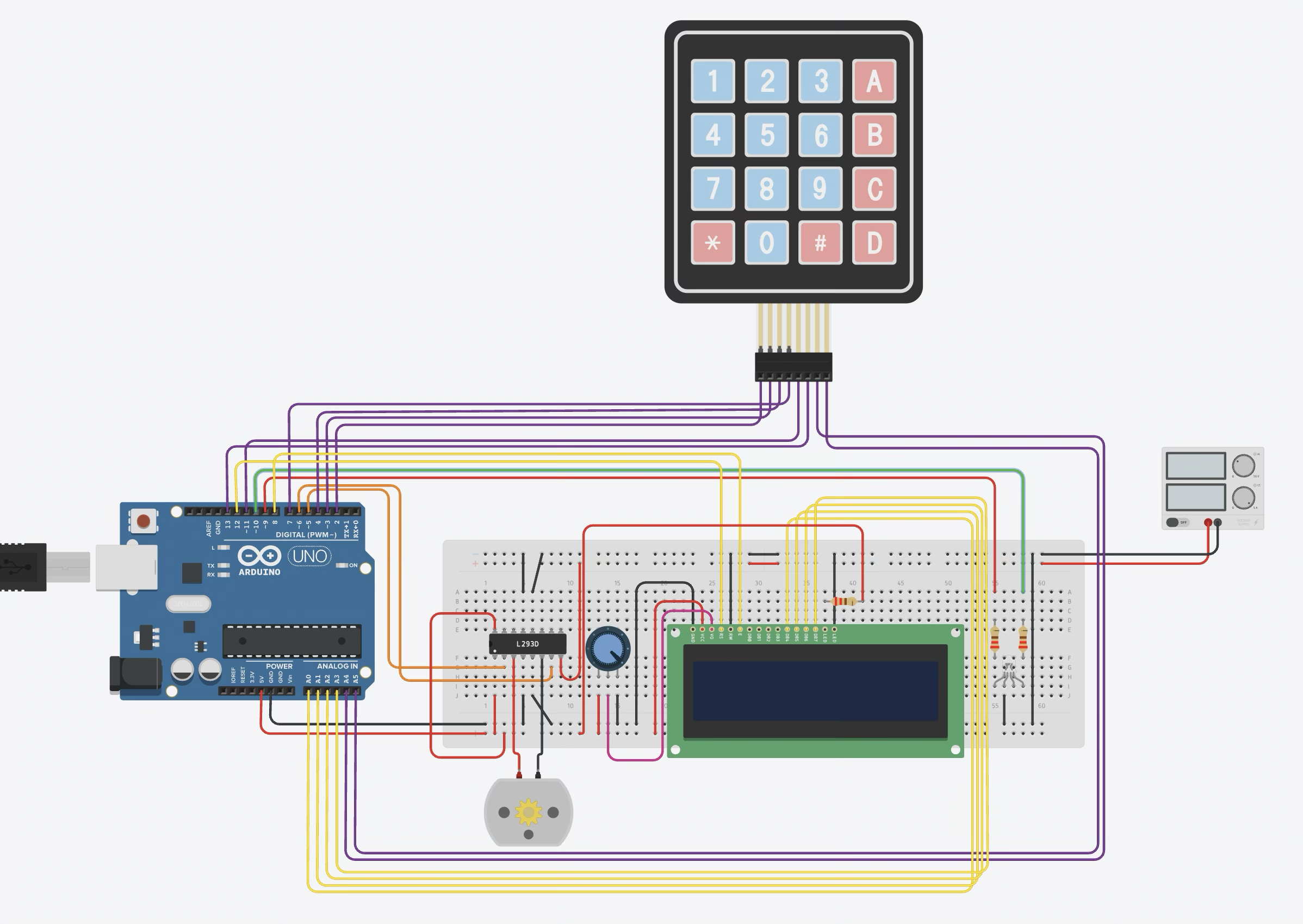
Keypad Motor Control Station
DEGREE OBJECTIVE 1
Design and complete robotic and embedded systems solutions that address real-world situations and challenges.
How it meets the objective: It implements the control pattern real industrial machines use — speed selection, direction control, live status, and an emergency stop that always works — as a complete, working embedded system.
Operating the station: keypad speed selection, direction reversal, start/pause, and the hard emergency stop, with live status on the LCD.
An operator control station for a DC motor: 4x4 matrix keypad input, L293D H-bridge drive, 16x2 LCD status display, and an emergency stop — the same pattern used on real conveyor and machine controls. Built in RBT173 with Arduino C++ and modeled in Tinkercad.
How it works
Keys 0–9 set a speed level mapped to PWM duty; # toggles start/pause; A reverses direction; and * is a hard stop that cuts both H-bridge inputs and clears state. The motor runs from a separate 9 V rail on the L293D's Vcc2 while logic stays on 5 V with a common ground. A 16x2 LCD shows run state, direction, and speed level in real time.
Engineering highlights
Safe-by-default state machine: the motor powers up stopped at speed 0, pauses the drive, and the hard stop forces both H-bridge inputs low before clearing the state.
Modular structure: input handling, motor drive, and LCD display are isolated into small, single-purpose functions, making the logic easy to test and extend.
Power discipline: separate motor and logic supplies with a shared ground — the same practice used to keep inductive noise off logic rails in real machines.
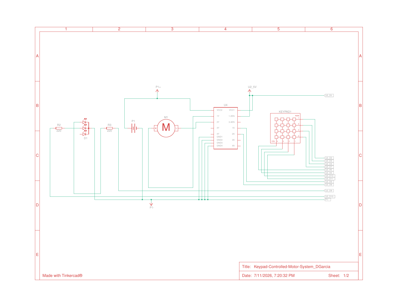
Motor drive sheet: L293D H-bridge, DC motor on its separate 9 V rail, and the 4x4 keypad matrix.
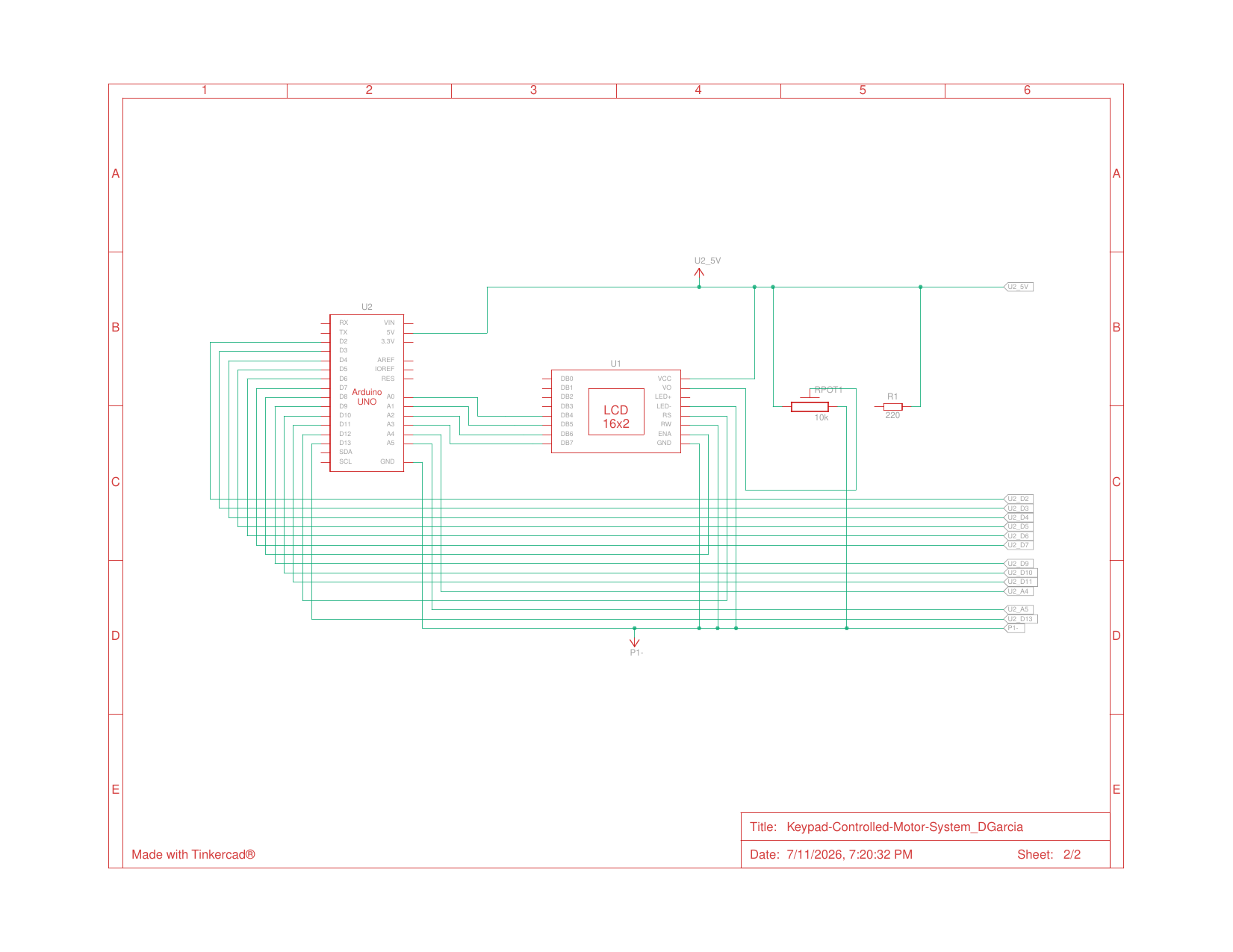
Operator display sheet: 16x2 LCD with contrast pot on the shared 5 V logic rail.