
BJT Transistor Switch
DEGREE OBJECTIVE 2
Demonstrate embedded microprocessor system and circuit skills.
How it meets the objective: It demonstrates circuit skills at the component level — calculating the transistor's base resistor from gain (HFE) and load current so one button reliably switches seven parallel LEDs, the same load-switching principle microcontrollers depend on to drive motors and pumps.
What I did
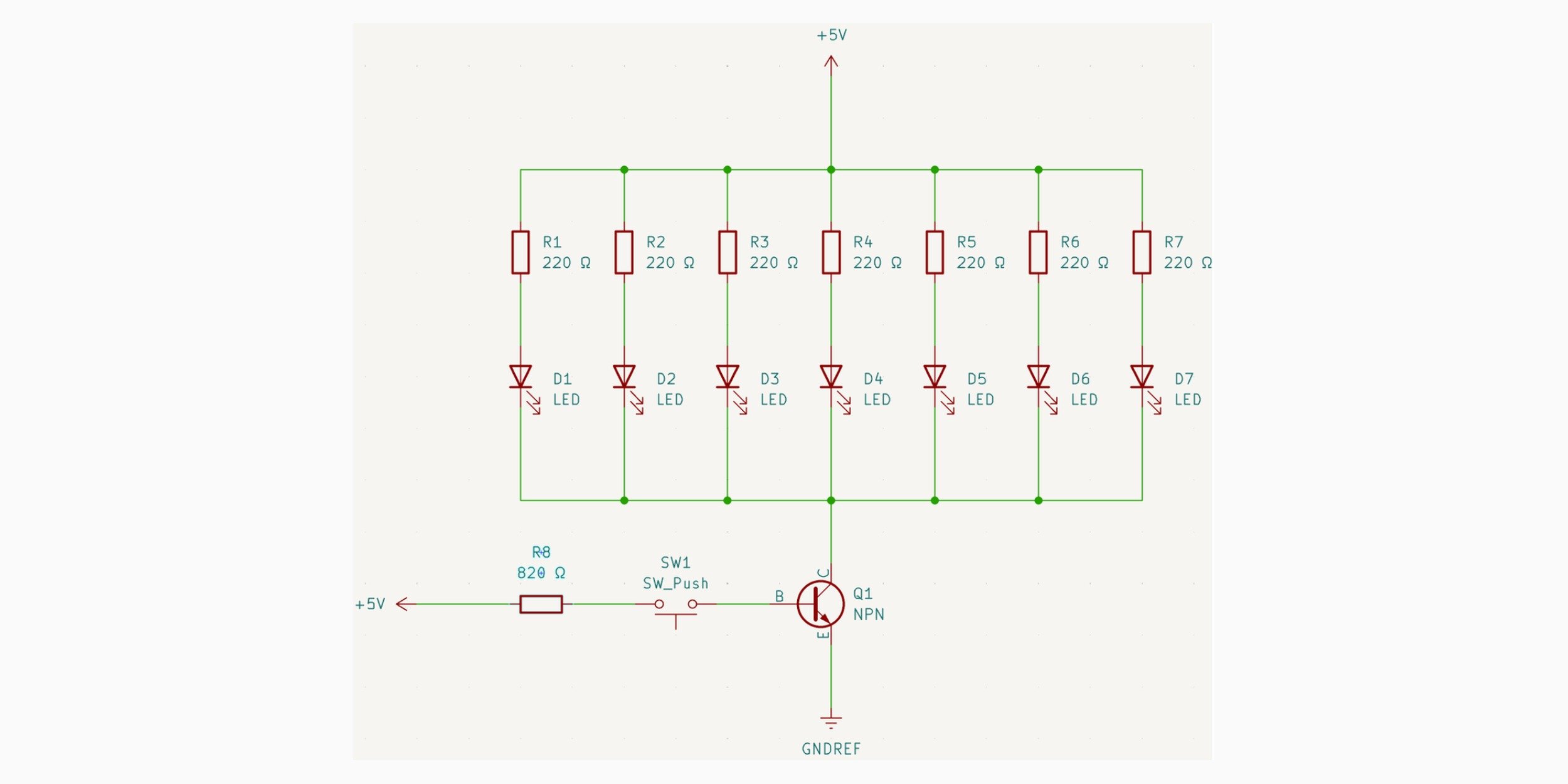
Built the switching circuit with seven blue LEDs in parallel on the collector side and a push button feeding the base through a current-limiting resistor. Calculated the base resistor from the transistor's HFE and the total collector-emitter current needed to saturate the switch, sized separately from the 220 Ω LED resistors. Documented the schematic in KiCad and verified the on/off behavior on the breadboard.
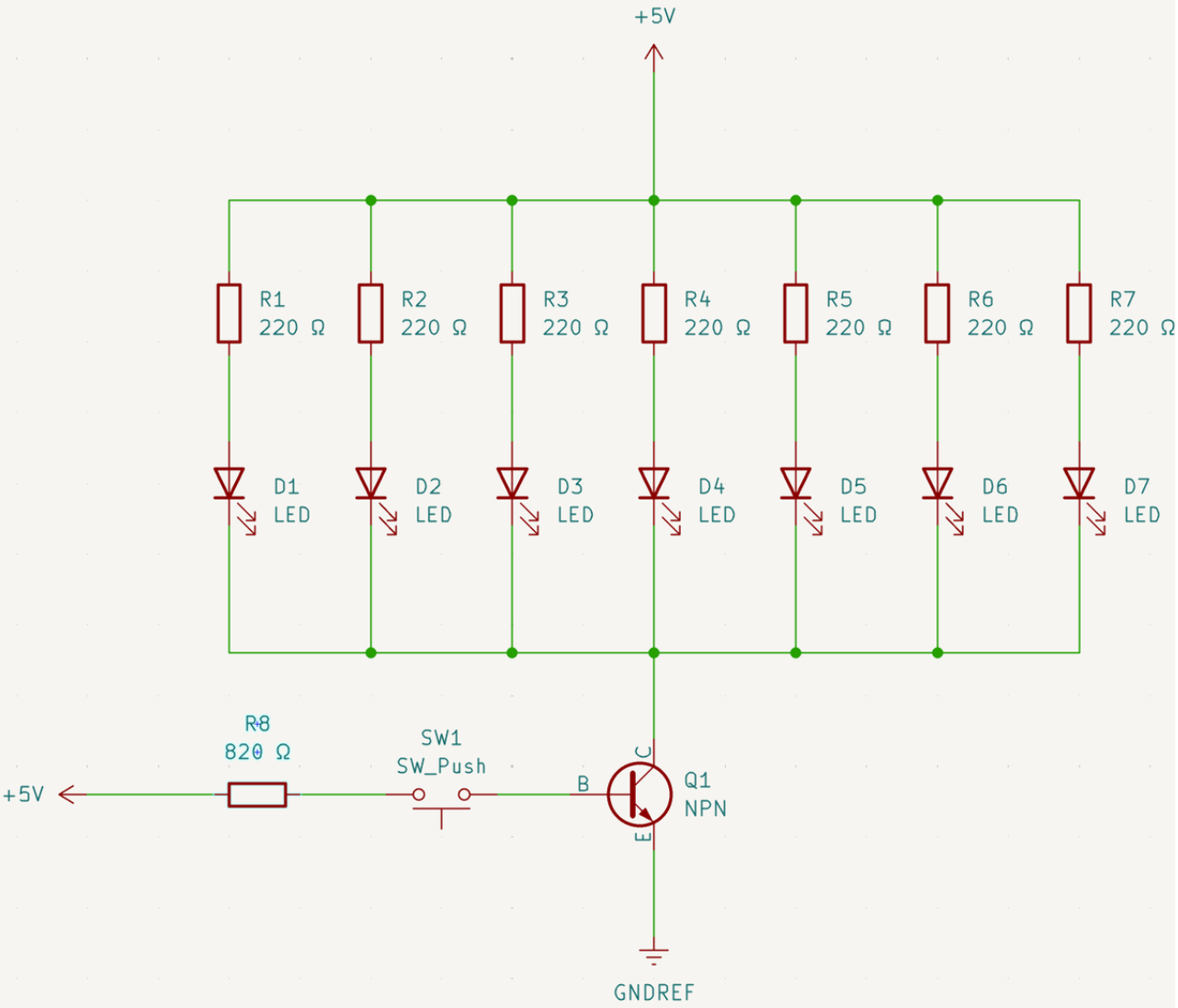
KiCad schematic: seven parallel LEDs on the collector side, the 2N2222, and the push button feeding the base through its current-limiting resistor.