
4-Bit Binary Adder
DEGREE OBJECTIVE 5
Model, analyze, and design systems or processes that integrate hardware and software to control autonomous mechanical systems.
How it meets the objective: It models the system with truth tables, designs it in gate-level logic, and verifies it against hand-worked arithmetic — the design-verify loop under every processor that controls a machine.
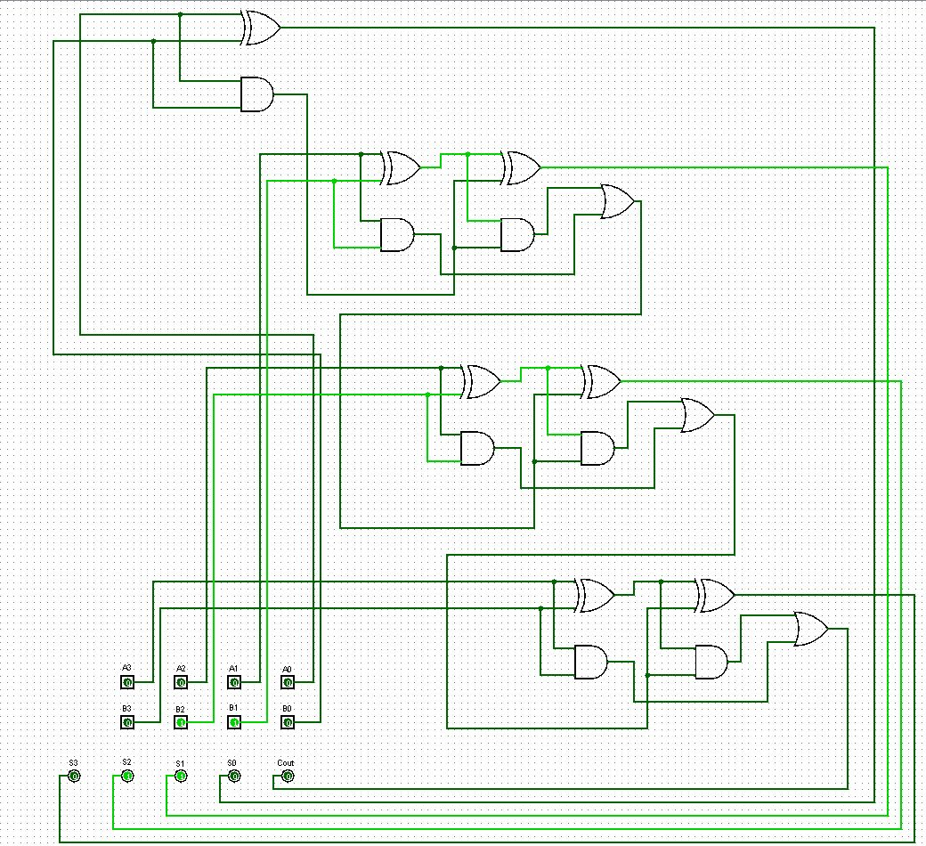
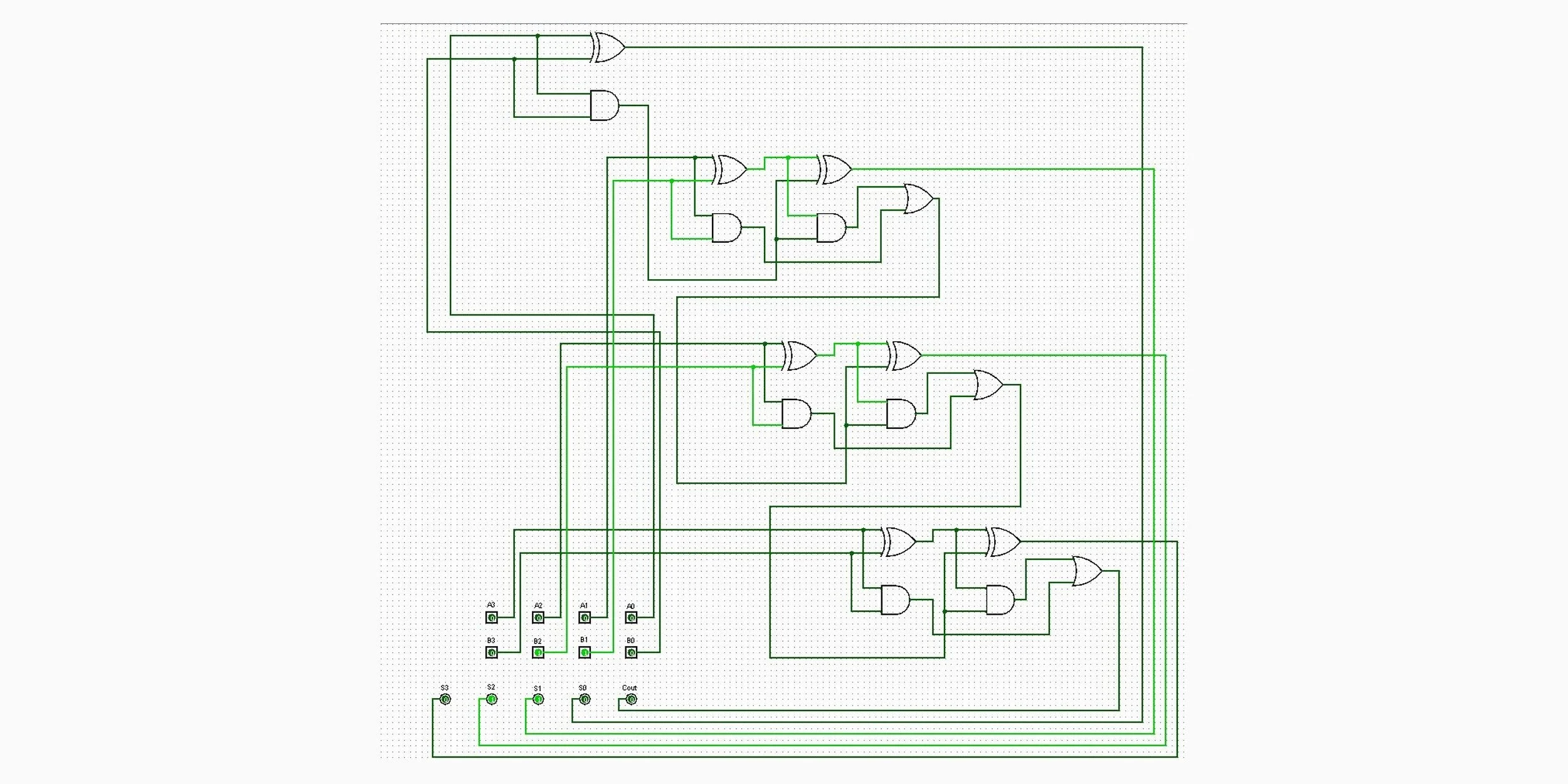
The full ripple-carry adder in Logisim: four chained full adders, each built from two half adders, with input pins A and B at lower left and the sum outputs and carry-out below.
A complete 4-bit ripple-carry adder designed in Logisim from first principles — built up from half adders to full adders using only AND, OR, and XOR gates, and verified against hand-worked binary arithmetic. Built as the RBT131 final project.
How it works
Two half adders combine to form a full adder; four full adders chain their carry-out to carry-in to form the 4-bit ripple-carry adder. The circuit takes two 4-bit inputs and outputs their 5-bit sum — the carry out of the top column is the fifth bit, worth 16, exactly like the carried "1" in paper addition. Verification ran ten input combinations with the binary arithmetic worked out by hand alongside the simulator output. My later work drives microcontrollers at the register level; this project is the foundation under that — what the ALU is physically doing when an ADD instruction executes.
A      B      Expected   Simulator   Match
0000   0110   00110      00110       yes
1011   1100   10111      10111       yes
1100   1101   11001      11001       yes
1101   1101   11010      11010       yes
Four of the ten verified cases — the full table is on GitHub.